
DBM (Database Manager)
DICOM (Digital Imaging and Communication in Medicine) is a standard format used in various medical imaging equipment. The DICOM protocol was established by the RSNA (Radiological Society of North America) meeting in 1992. Since then, working groups of the ACR-NEMA (American College of Radiology – National Electrical Manufacturers’ Association) have been established to work on international standardization. Currently, DICOM 3.0 has been made public and consolidated as the standard format for medical image files and inter-equipment networking.
Today, most medical or dental imaging equipment utilize DICOM format, and OnDemand3D™ is no exception. OnDemand3D™ lets you import DICOM data to your local database or a remote location such as [OnDemand3D Server] or a [Remote PACS Server]. In addition to supporting both multi-frame and split-frame DICOM data, users will be able to convert one from the other straight on OnDemand3D™
Layout
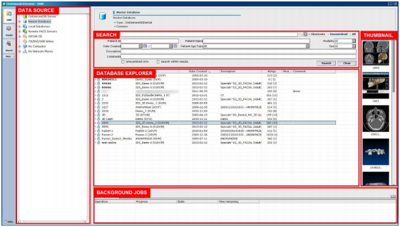
[Data Source] – List of available data sources
[Search] – Search through data using the options available
[Database Explorer] – List of DICOM data from the currently selected Data Source or search results
[Thumbnail] – A preview of the DICOM data and Project Files contained in the patient study
[Background Jobs] – List of importing or exporting jobs in the background
Data Sources
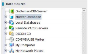
The DBM module acts as a database explorer to import to and export from on OnDemand3D™ Dental.
OnDemand3D™ Server
Users are able to save patient data and Project Files on OnDemand3D™ Server, which would be accessible from other workplaces as long as an Internet connection is available. For more info on how to purchase, please contact local distributor or ontact us directly at [email protected] and visit our website at www.ondemand3d.com
To load DICOM files saved on OnDemand3D™ Server, click the [OnDemand3D–Server] icon in the [Data Source] window. When the [Server Log-in] window appears, as shown in Fig. 21, input User ID, Password, Server Address (Server Computer ID) and press [Connect].
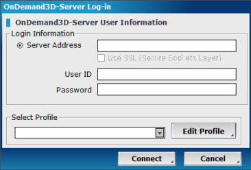
When using multiple servers, users can simply make a profile for each server and then log-in using the [Select Profile] menu for easier access. To add or edit server profiles for easier access, click on the edit profile button.
Master Database
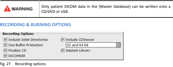
The [Master Database] is a user’s own database on a certain workstation. This database will not be affected by software updates. The user can run DICOM CD/DVDs or USB discs and import the data onto their [Master Database].
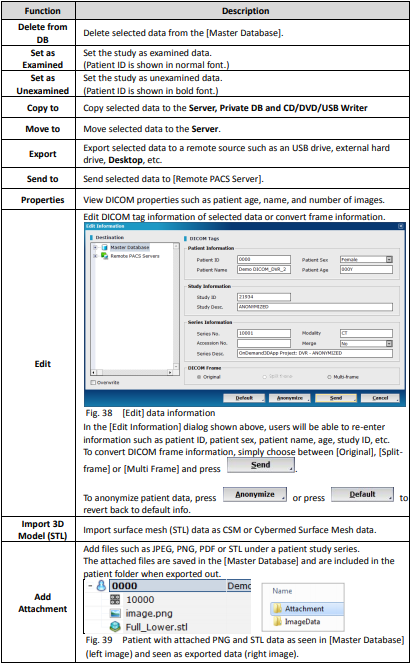
Import data by a simple drag and drop motion or right-click and select [Import]. Users can also set the depth of sub-directories to be imported by selecting [Import depth]. Attach patient-related files, such as STL, PDF, images, and X-report data to the patient study by right-clicking on selecting [Attachment]. When the patient study is exported, a separate [Attachment] folder containing all attachments will be created.
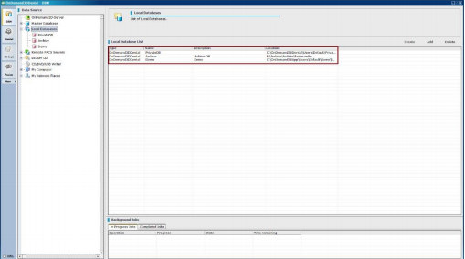
Local Databases
Local Databases have an archiving feature and are used when the current default [Master Database] is becoming too large or reaches a specific threshold, which in its turn slows down the process and cause difficulties finding particular patient data or sift through the patients’ data.
Users can create their own local database, archive and relocate existing [Master Database] data to a secure drive with more space by simply right clicking and selecting whether to create new database or add an existing one. All the functions and features of the [Master Database] such as importing data by a simple drag and drop, patient-related files attachment, saving the data onto the local databases are
available. [PrivateDB] is the default setting in the [Local Database] and can be disabled.
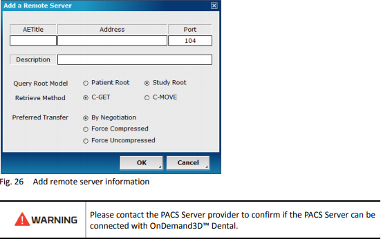
Remote PACS Server
Right-click on the [Remote PACS Servers] and select [Add a Remote Server], as shown in Fig. 25, to add a remote server.
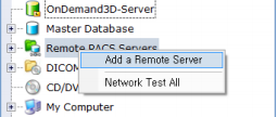
Input the AE Title, IP Address, Port number into the corresponding fields, and press [OK].
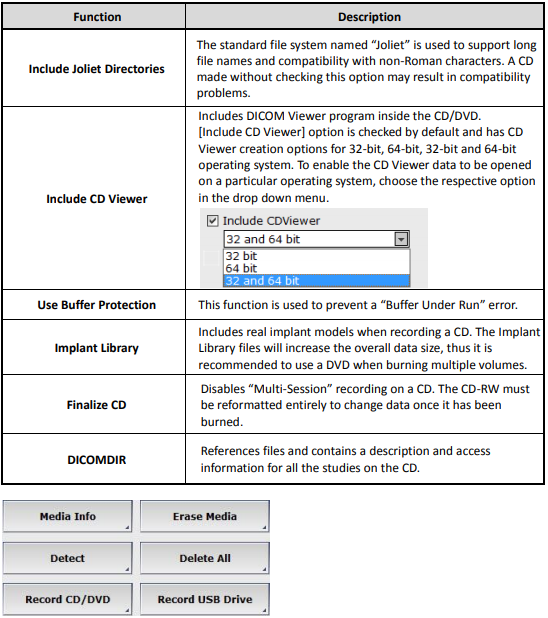
DICOM CD
DICOM data stored on a CD/DVD can be imported onto the user’s [Master Database] or viewed directly. Insert a DICOM CD/DVD into the computer disc drive, and the DICOM CD/DVD information will automatically appear in the [Data Source] section underneath [DICOM CD].

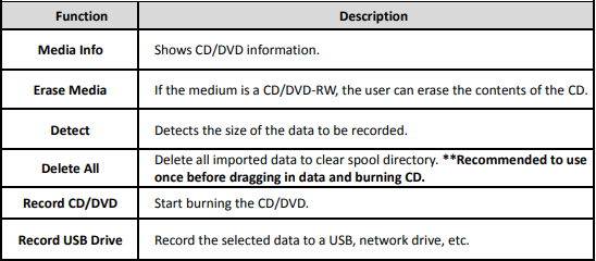
CD/DVD/USB Writer
A backup CD can be created using OnDemand3D™ if there is a CD/DVD-R or CD/DVD-RW driver installed on the computer. From the [Master Database], select the desired patient data and drag it into the [CD/DVD/USB Writer] tab in the [Data Source] window.
My Computer and Network Places
Click on [My Computer] to view or import/export data stored on the computer or click [My Network Places] to view folders or other computers linked through the local network.
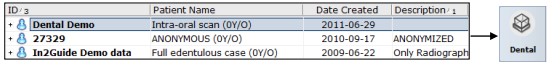
Database Explorer
The [Database Explorer] shows DICOM data from the selected [Data Source]. The user will be able to import/export patient data or select patient data to load onto a module from this section.
To start treatment planning or patient diagnosis and analysis, first click on the patient data in the [Database Explorer] and then click on a module of choice.
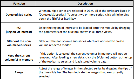
DICOM [Loading Options]
When patient data is loaded onto a module, the [Loading Options] dialog shown in Fig. 34 should pop up.
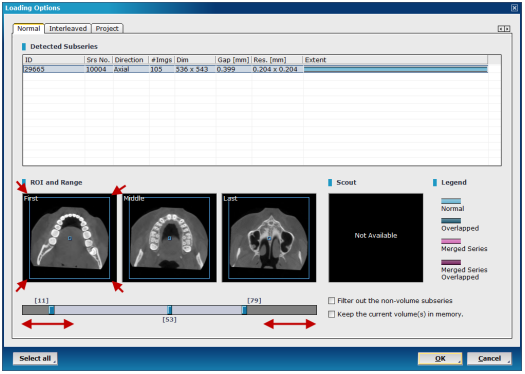
Fig. 34 If necessary, use the blue rectangular outline provided on the [ROI and Range] images interest and the slider bar provided at the bottom to adjust region and range of interest.
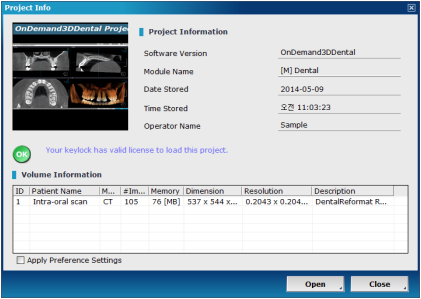
Project File Info
Double click on a Project File from [Database Explorer] to load. When the [Project Info] window appears, as shown in Fig. 35, click [Open] to load the Project File with the corresponding DICOM data.
DICOM [Database Explorer] Options
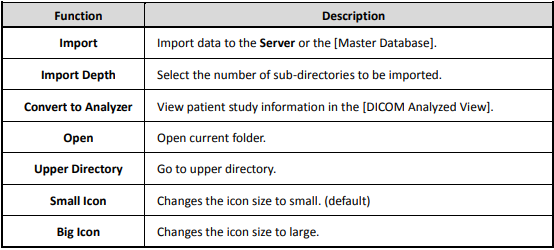
Right-clicking on a DICOM folder in [Simple File View] will show the following drop-down menu.
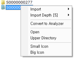
DICOM folder drop-down menu
Right-click on a patient series in [Database Explorer] and see the following menu:
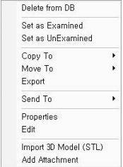
Patient series ‘drop down menu’
Thumbnail
When a patient series is selected in the [Database Explorer] window, the user should see a preview of the data contained in the [Thumbnail] section of the DBM layout. The [Thumbnail] section previews DICOM data, Project Files, reports, and imported STL data.

Background Jobs
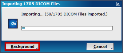
When an [Import] command is given, the following dialog will pop up. OnDemand3D™ will not be accessible when this pop up is open, so please click on to collapse it to the bottom of the screen
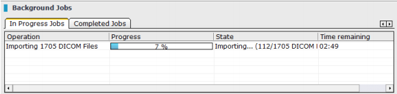
[In Progress Jobs] running in the background
General Tools
These tools include some of the most used on OnDemand3D™ and are included in all of the available modules. They are displayed right alongside the module on the left side of the screen.
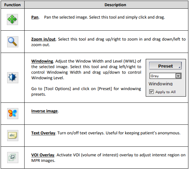
Viewing Tools
Measuring Tools
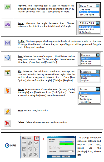
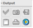
Output Tools
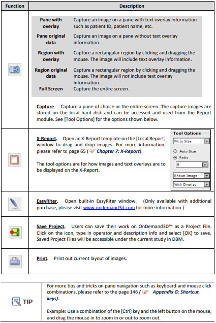
Additional Tools
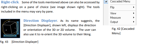
Image Options
Image rendering options and filter options are available on the top right corner of each pane and along the top bar of OnDemand3D™. Window-Width/ Window-Level and Zoom information are displayed on the bottom right corner of each pane.
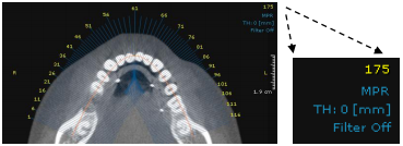
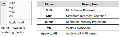
Rendering mode. The number 175 in Fig. 44, shown above, stands for the slice number, while [MPR] is the currently set rendering mode. To change settings, click on the [MPR] text and the menu below should pop up.
Slice thickness. The slice thickness can also be adjusted by clicking on the [TH: 0 [mm]] text and inputting a value manually or selecting a value from the drop down menu. To set a default slice thickness on OnDemand3D™
Sharpening filters. Users can enhance the quality of image data by using the sharpening tool provided. Click on the [Filter Off] text in the image pane or select from the top bar of OnDemand3D™ to sharpen the image. (Note: Unlike [Filter Off], [Filter] button sharpens images in all MPR panes.)
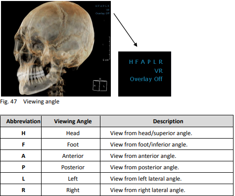
Viewing angle [3D Volumes]. For 3D image panes, users will be able to choose the direction the 3D Volume faces.
Overlay settings.
Users can choose to view different types of overlays, for example the
MPR overlay, Plane overlay and Outline overlay.
Windowing and Zoom.
Windowing width, windowing level and zoom ratio value
information are all shown on the lower right corners of each pane
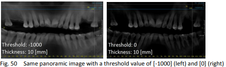
Threshold. Threshold options are available in the Panorama pane. Users can set a minimum density value to display. If the threshold value is set to ‘0’, only the regions with the density value of ‘0’ or higher will be displayed.
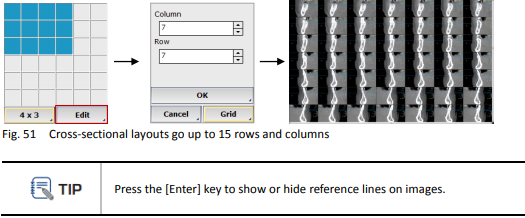
Cross-Sectional Layout. The number of slices shown in the CrossSectional or
Panorama panes can be set by the user. Click the icon choose desired layout. Users will also be able to click and manually enter the number of cross-sectional images wanted as shown below.
Maximize and Minimize. Click the icon on the top right corner of the pane. The
window will maximize to fit the screen. The Panorama pane spreads horizontally and hides the 3Dpane when it is maximized.
Additional commands. For 2D panes, click the icon on the top right corner of the
pane to flip the image. For 3D panes, there will be additional tools for changing rendering speed settings and background color.
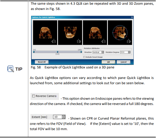
Quick LightBox [QLB]
Quick LightBox is tool that provides the user with a quick review of a series of images that can be easily scrolled through, along with some handy tools such as the Cine Player function, which can generateand export video AVI data from image files.
Quick LightBox, launched from a 2D pane, can provide the user with a series of slice images accordingto the slice thickness, spacing and rotation the user has set, while launched from a 3D pane, it canshow the 3D volume in a series of images depicting a rotation along parameters also set by the user.
Launching Quick LightBox
Users can access QLB using the icon provided on the top right corner of certain panes. Click on the QLB icon to view the [Options for Quick LightBox] window shown below. Users can select their region of interest using the slide bar provided and the slice spacing and thickness settings on the [Translation] tab. The [Rotation] tab lets the user choose between a [Horizontal] and [Vertical] slice angle. Set the [Rotation Degree] values between each slice. If the [Rotation Degree] value is set as ‘5’, the
angle between each slice will be 5 degrees.
Click [OK] to launch Quick LightBox with the current settings.
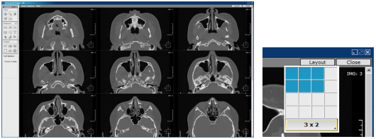
Click on [Layout] in the utmost right corner to change the number of images displayed and scroll through the slices for a quick overview.
Cine Player
 There is one additional [Output] tool in QLB called the [Cine Player].
Users can generate a video file using the image data currently loaded onto Quick LightBox. Click the icon to see the window
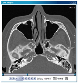
Use the tools provided at the bottom of the player window.
The user can set speed and playback settings with the menus provided.
Export the video file as AVI data using the icon
Dental
OnDemand3D™ Dental is designed for private dental offices with CBCT equipment. Dental contains essential functions needed to view DICOM images aiding dentists with higher precision, better implant and treatment planning and most of all, accurate diagnosis.
Layout
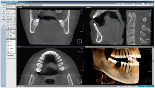
The default layout of the Dental module is [MPR]. The user can come back to this screen at anytime using the [3D MPR] tool in task toolbar. The five different tabs in the Dental module, as shown below, are: [MPR], [Dental], [TMJ], [Bilateral TMJ] and [Verification].
![]()
MPR
The [MPR] layout has four Task Tools.
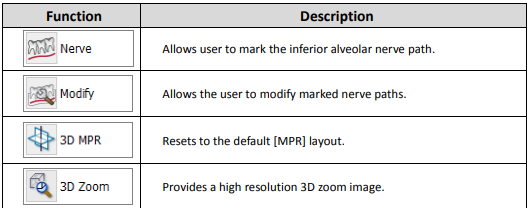
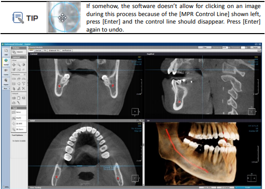
Nerve. The [MPR] layout allows you to mark the inferior alveolar nerve path using the coronal, axial and sagittal views. Click on [Nerve] and place the first point, scroll through the views and click once on each point to continue the path, and click twice to finish drawing. To start over while drawing, click [Esc].
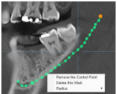 Modify. To modify or make adjustments to the drawn nerve, click on [Modify] from [Task Tools] and reposition the nerve markers one by one or delete the whole path. Right-click on a nerve marker for more options, as shown below.
Modify nerve markers (control points)
3D MPR. Resets changes made with the [3D Zoom] tool and goes back to the default layout.
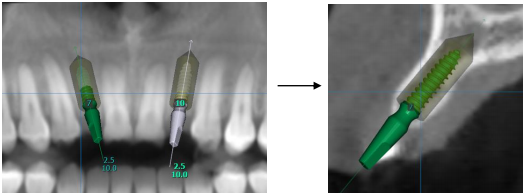
3D Zoom. This tool allows the user to zoom in on a specific region in high resolution. Different from simple magnification, it re-renders the selected area as to minimize loss in resolution. 3D Zoom can be utilized in viewing the finer structures of the whole anatomy.
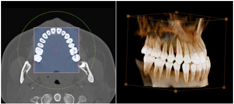
Fig. 63 3D zoom function
Click on [3D Zoom] and click on the area to zoom in on. Drag the area out as far as needed. After the cube has been drawn, click on the red [x] in the middle to move the cube to a different region and drag out the green circle to expand the area.
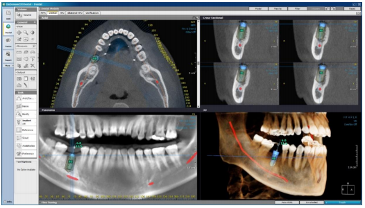
Dental
The [Dental] tab consists of 4 different panes: Axial, CrossSectional, Panorama and 3D.
Task Tools
The Dental tab has the following tools available:
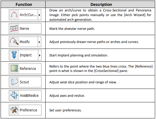
Arch/Curve. This tool is used to generate panoramic and cross-sectional images.
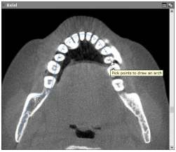 Select [Arch/Curve] from [Task Tools] and click on a starting point.
Click along the arch and then double click to finish drawing.
Panoramic and cross-sectional images will be automatically generated using the arch drawn by the user.
For automated arch generation, go to an axial slice where the full arch is visible and click and select . The low bound tooth density settings can also be changed for better results if needed.
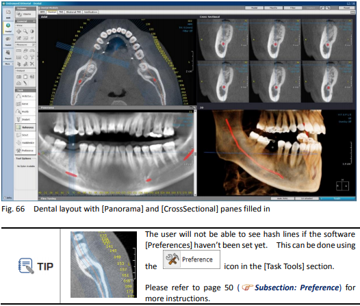
After the arch is drawn, the layout will fill in the images for the Cross Sectional and Panorama panes, as shown below.
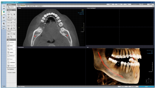
Nerve. The [Nerve] tool enables users to draw along the inferior alveolar nerve path, which isvital for treatment planning and diagnoses. Users can utilize any of the panes available. Select [Nerve], click along the path to draw, as shown in the image below, and double-click to finish. To start over, click [Esc] on your keyboard.
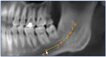
The most widely used pane for drawing along the nerve path is the [Panorama] pane. The optimal level of slice thickness, same as the image above, is 10 mm. However, the more accurate but slower method is to use the [Cross Sectional] and [Axial] panes.
To draw using the [CrossSectional] pane, select [Nerve] from the [Task Tools] menu and click on a starting point in the [CrossSectional] pane as shown below. Scroll using mouse scroll-wheel and click on the next connecting point. The same process can be repeated on the [Axial] pane.
After the nerve is drawn, the marked nerve path will be highlighted and visible in all of the panes on the layout. The color and visibility can also be set in the [Preferences] menu in the [Task Tools] section.
Modify. To make modifications to the drawn nerve path or the arch, click on [Modify] and select either one. As shown below, the points along the path can now be manipulated.
Reposition control points one by one or move the entire arch. Users can also right-click and insert additional control points, delete selected control points, or delete the whole arch. The same goes for nerve paths. Modify nerve markers as shown on [Panorama] (right) and [Axial] (left) panes Press [Esc] when finished.
Implant. The Dental tab allows for implant planning and surgery simulation. OnDemand3D™’s implant library includes real-size implant fixtures and abutments from all major manufacturers. Some of the analysis tools available on this tab are [Bone Density Graph] and [Angle].
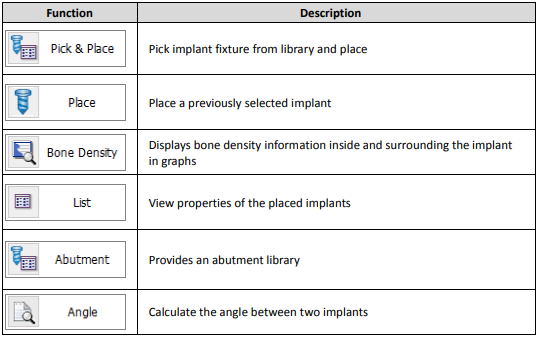
Pick and Place. The [Implant Library] window as shown in Fig. 72 provides the user with a Manufacturers list, a Product Lines list, a Preview window and a section where the individuals implant models are to be selected from.
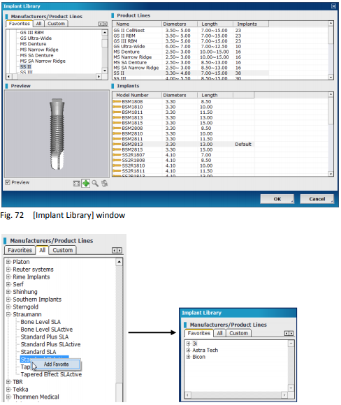
In the ‘Manufacturers’ section, the user will find three tabs: [Favorites], [All], and [Custom]. To add a product line or implant to [Favorites], right click and choose [Add Favorite]. Users can also create their own implants by going to the [Custom] tab and clicking on. In the [New Implant] window shown in Fig. 74, input the naming and parameter settings of the new implant and press [OK].
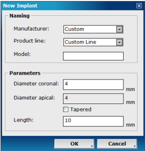
Create custom implants using the [New Implant] window
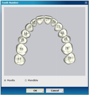
Place. To place an implant fixture, click on the area where the virtual implant is to be placed and select the corresponding tooth number when the dialog below pops up. The default tooth numbering system can be changed in the [Preference] menu when needed.
Afterthe implant fixture has been inserted, users can adjust and move it accordingly, using their mouse.
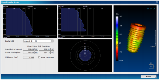
Bone Density Graph. This tool provides graphs on the bone density information for each implant. This information is displayed in two viewing directions: Coronal-Apical (the two graphs on the top) and the Implant Perpendicular direction (the lower graph). Click [Bone Density] graph from [Implant Task Tools] and choose the ID of the implant in question.
Users will be able to see bone density information of both the inside and outside of the implant fixture. [Thickness] refers to the thickness of the shell around the implant that is used to gather bone density values. Any changes made to the implant while the [Bone Density Graph] is still open will be immediately registered and updated on the graph.
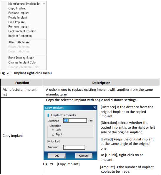
For more options, users can right click on an implant fixture, and the following drop-down menu will appear.
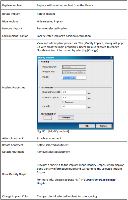
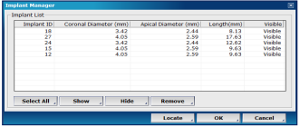
List. This tool provides information on all of the currently placed implants including implant ID, apical/coronal diameters, and the length of each implant. [Show], [Hide], [Remove] or [Locate] all from this window.
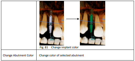
Abutment. Users can place abutments on implant fixtures from our library.
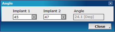
Angle. A tool that calculates the angle between any two implants. Select two implants from the menu, and the [Angle] values will be automatically calculated.
Reference. The point where the two blue lines cross is called the [Reference] point, and this is what is shown in the [CrossSectional] pane. For a closer look, users can first choose [Reference] from [Task Tools] and then click wherever they need. It is recommended to use this tool before an implant fixture is placed.
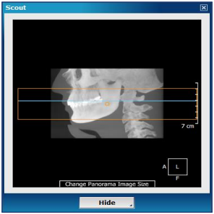
Scout. Users can use the [Scout] image as a guide to switch to a different axial slice or to reslice the data to include less of the whole CT data. As seen in Fig. 85, the blue line refers to the axial slice position. The area within the orange rectangle is the area of interest for the user. If a full skull view is not needed, users can set their area of interest by expanding or shrinking the orange rectangle.
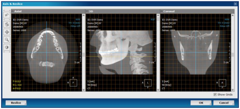
Axis & Reslice. This tool is used to make adjustments to the axes of CT data. Drag the blue reference lines to readjust and click [Reslice] to reslice. For easier viewing, don’t forget to make use of the grid by checking [Show Grids]. Rotation degrees will be shown in yellow on the [Axial] pane, while the yellow line on the 3D pane refers to the horizontal plane of the teeth. Please note that in case the user chooses to reslice, most of the layout settings will be lost along with any pre-drawn arch information.
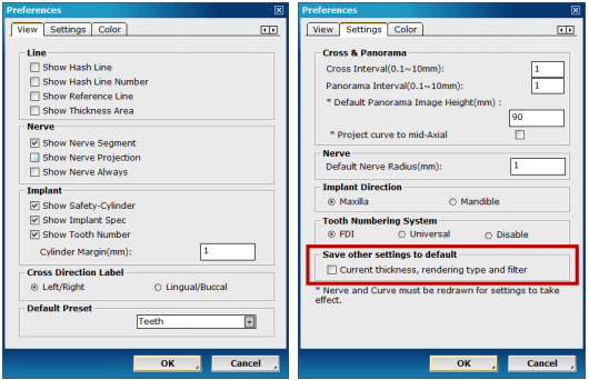
Preferences. Most of the user’s software preferences are set in this menu and are saved for all future projects.
As can be seen below, the [Preferences] menu has three tabs: [View], [Settings], and [Color]. In the default [View] tab, users will be able to set preferences for whether they want to be able to see hash lines, nerve segments, implant safety cylinders, etc.
In the [Settings] tab, users will find more advanced settings such as the default radius of the nerve in millimeters and tooth numbering system settings. To change the colors of curves, nerves and reference lines, please refer to the [Color] tab.
Additional Tools
For intra-oral/3D model scan alignment, users can use [Model] and [Maxilla] buttons provided on the top gray bar of the Dental tab.
Align
The [Align] function is characterized as merging intra-oral scan/3D model scan to the patient DICOM data. The following is a representation of the user’s workflow on intra-oral scan/3D model scan alignment with patient DICOM data.
Step 1: Click msxilla on the top gray bar and select volume clipping direction by choosing [Maxilla] or [Mandible]. When in the [Align Model Wizard Step] adjust how much of a volume to clip using scrollbar on the left of the 3D pane.
Step 2: Click MODEL and select [Align] .
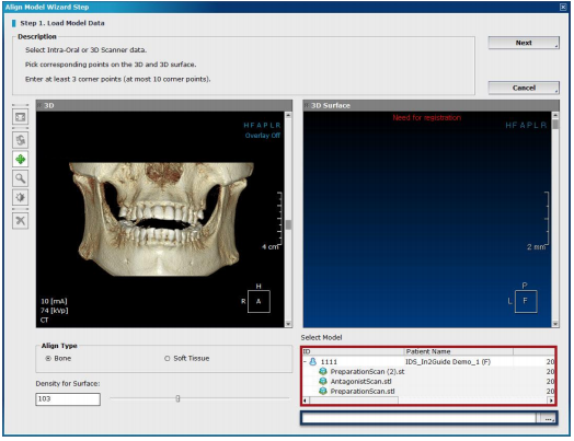
Step 3: Load Model Data (Step 1 of the Align Model Wizard Step).
Load intra-oral/3D model STL file straight from the DBM or click button at the bottom-right hand corner (see Fig 89 highlighted in red and blue respectively) and locate file on your PC.
Step 3 (A): Select Align Type. Select either Bone or Soft Tissue for the DICOM data.
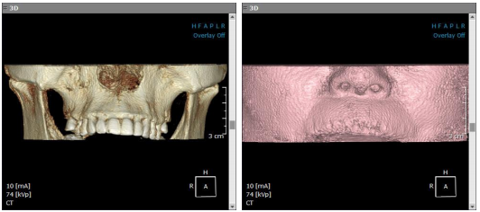
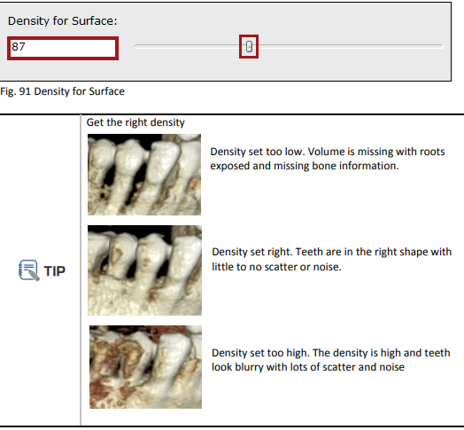
Step 3 (B): Density for Surface Adjustment.
Using [Density for Surface] adjust the density (threshold) settings to create a clear image of the patient. Scroll the density bar left and right to adjust the density value. To achieve the best result adjust for the clearest image of the patient with minimum scatter and noise.
Step 4: Picking corresponding points.
After loading STL data and adjusting Align Type along with Density for Surface, double click on each dataset to pick three to ten corresponding points from the 3D and 3D Surface.
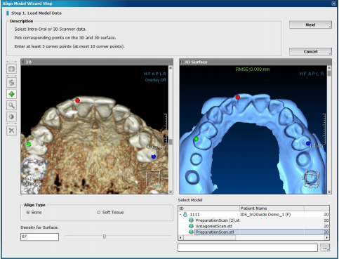
Use the toolbar on the left of the Align Model Wizard Step window to reset, rotate, pan, zoom in/out, adjust windowing, as well as remove all SR points.
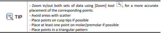
The RMSE (Root Mean Square Error) must be under 2.000 (mm) in order to proceed with alignment and achieve accurate results. The RMSE value will change to green once the corresponding points are in the acceptable RMSE range. If not, it will be shown in red. In general, RMSE under 0.200 (mm) is recommended for best results.
Step 5: Click next to proceed or click [Cancel] to close Align Model Wizard Step window
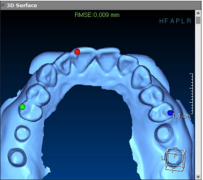
Step 6: Finish (Step 2 of the Align Model Wizard Step).
Verify the alignment at the final step by scrolling through the Axial and Cross-Sectional views and making sure STL data is tightly in contact with the patient data. The blue contour on the Axial and Cross-Sectional panes indicates the STL data, as shown in Fig 94. Once the contour is verified, click OK to finish the alignment.
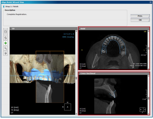
3D Model
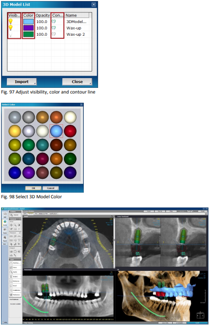
Click MODEL and select to check 3D model and edit the list of 3D models available.
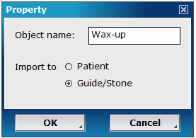
Click import to import 3D model onto the aligned data. Input object name and choose whether to import 3D model onto the [Patient] data or onto the [Guide/Stone] which is previously aligned STL data.
[Visibility], [Color] and [Contour line] of the imported 3D models can be adjusted according to the user’s preferences. To change aforementioned settings simply click on the light bulb to change the visibility, color bar to change the color as seen in Fig. 98 and tooth icon to change the contour line.
TMJ
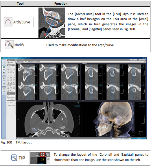
The TMJ layout is designed so that users can study the Temporomandibular Joint with the four different views available: Axial, 3D, Coronal and Sagittal. There are two available task tools in the [TMJ] layout.
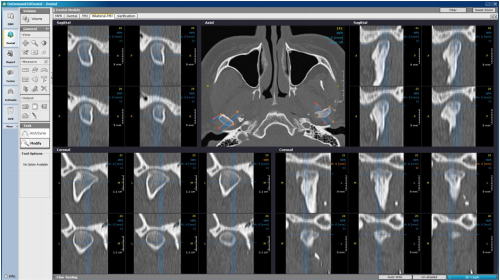
Bilateral TMJ
The [Bilateral TMJ] layout mirrors the already drawn arch/curve on the [TMJ] layout on the other side. Use the [Modify] tool from [Task Tools] to make changes to the arch/curve.
Verification
The [Verification] tab is for verifying the placement of simulated implants. An [Implant Cross] and [Implant Parallel] panes are included in this layout for a much more precise planning.
To access [Verification] for specific implants, the user can click on an implant first on the [Dental] tab and then click on the [Verification] tab or simply right-click on an implant and select [Verification]. For more than one implants, users can switch between them using the implant ID on the provided toolbar located above the four panes, as shown below.
The icon shown in Fig.103 refers to the reorientation of implants.
The user will be able to see four arrows surrounding the selected implant, and two arrows outside for precise rotations in the [Implant Parallel] pane. The distance the implant is moved in each direction by one click, and degrees the implant is rotated by one click can all be set using the settings. Any changes made can also be reversed using the icons. The [Verification] tab has only two task tools:
[Axis/Reslice] for reslicing DICOM data and resetting the axes.
[Preferences] accesses the software preference settings.