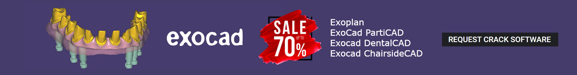

Report
The Report module is for users who want to quickly create a simple report. The Report module supports the extended functions of capture, save, convert, and print reconstructed images from OnDemand3D™. In addition, it lets the user export the created report as an HTML formatted document for viewing on any computer. Images ‘captured’ from other modules with the tool can be accessed here.
Layout
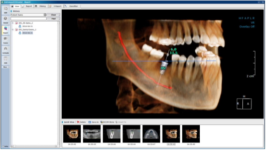
View previously captured images by patient and date on the Report [View] layout
The user will be able to switch between modes using the tab buttons at the top of the screen, shown below.
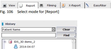
The user’s history of captured images are saved and stored in the [History] section, through which the user can search by date, patient ID and patient name.
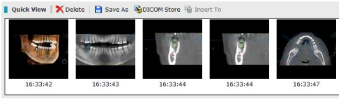
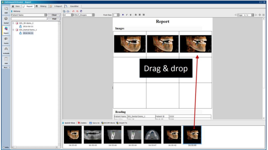
When a folder is selected in the [History] section, the user will be able to see a preview of the images contained in the [Quick View] section as shown. In the [Quick View] sections, users will be able to [Delete], [Save], [Store images as DICOM], and [Insert] selected images into the report. Simply dragging and dropping images into image slots on the report will work too.
Report
Use the [Report] tab for basic reporting using captured images.
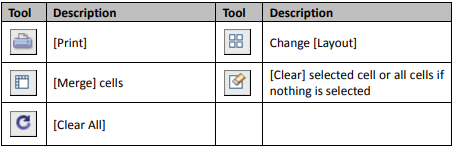
OnDemand3D™ provides the following tools for reports.
![]()
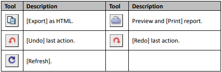
Select paper size for the report and the image layout using the and set font size, text styles, and text alignment.
The [Reading] section will be automatically populated with patient information when captured images are inserted into the Report, as can be seen below.
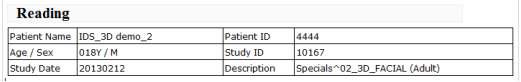
All of the information above can be edited if necessary
Filming
This mode allows users to choose an image layout and print out DICOM on film using a DICOM Printer. Drag and drop captured images onto the template layout and print.
Use the tools provided and drag and drop images onto the template
Printer Options
Users will see the following dialog when they click [Print]. Select your medium type and the scale of the report to paper. [Fit to Size] will automatically resize the report to fit the paper, while [True Size], the default setting, will print the report in its original size. Choose [User Scale] to manually set.

[Printer] options
Press add , shown in red above, to add a new DICOM printer.
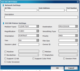 Manually enter network and DICOM printer
information, such as [Host Address] and [Port number]. Choose a page range, page count and size scale preferences. Users will also be able to choose between paper, clear film and blue film for their [Medium Type].
Add printer information
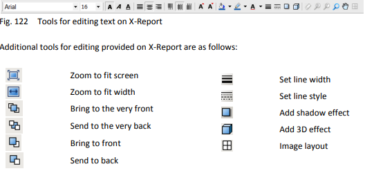
X-Report
X-Report provided by OnDemand3D™ is based on XML, while basic reports generated with the Report module are based on HTML. This makes it a much more advanced option for users who would like to create their own custom templates to increase efficiency and ease.
Custom templates created using X-Report Template Designer, detailed in the second part of this chapter starting on page 69 ( Section 7.2: X-Report Template Designer), can be accessed from any module on OnDemand3D™. Users will be able to easily insert images onto the report using simple drag and drop motions. X-Report also supports real-size printing and can be exported as PPT, HTML or PDF files
X-Report Tool
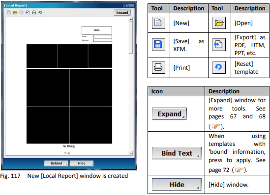
Load patient data onto any module, press from [Output Tools] and click in the [Local Report] window, as shown below.
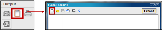
Create new report with template
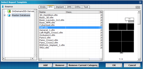
Template files are saved as XFM data
To add X-Report templates in XFM format saved on the computer, users can also choose to [Add].
Select a template from the desired category and press [OK] to see it generated in the [Local Report] window as shown
Inserting Images
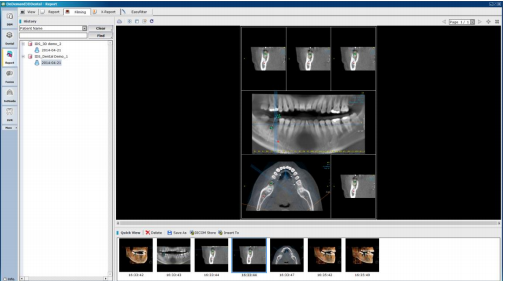
To insert images, simply drag and drop from the screen onto image boxes on the report. For cross-sectional images, OnDemand3D™ allows for inserting a series of images into the report at once. Users can do this by simply changing the layout of the [CrossSectional] pane to show more images and dragging the first image into the report. The image boxes after it will automatically fill.
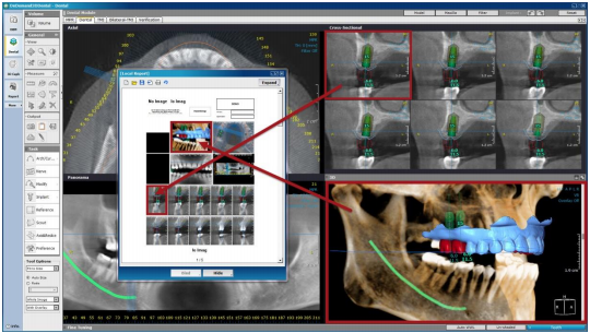
Simply drag and drop images onto image boxes on the [Local Report] window
Another way to import a series of images is to click on the images wanted to select and then to drag the first image in. The selected images following will automatically fill in. When a cross-sectional image is selected, users will see a light gray check mark on the image.
Tool options
Users also have tool options for this function, as can be seen below the [Task Tools] section
This image options menu contains settings specifically for the X-Report window. Select here, if the images to be dragged in are to be ‘shown size’, ‘true size’ or ‘fit to size’.
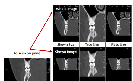
Comparison of original image in pane and images in X-Report with different options selected
[Shown Size] – the image will be the same size as shown in the actual OnDemand3D™ pane.
[True Size] – the image will true to its original size.
[Fit to Size] – the whole image will resized to fit the image box.
The [Auto Size] and [Ratio] settings refer to the text settings of the image being dragged. If there are text overlays on the image, such as measurements and notes or even patient information and ruler numbers, they will be automatically resized according to the image box size on the X-Report. Choose [Ratio] in order to manually set the resizing ratio.
[Whole Image] will import the whole image, rather than the portion of the image that is visible in the pane (user’s zoom settings), while [Shown Image] will only import the shown portion of the image. For image overlays to still be visible in the report, select [With Overlay] and select [Image Only] to import the image without any overlays. Overlays include text overlays such as patient information, measurements, reference lines, and plane/outline overlays.
[Expand] window
[Expand] the window using the icon and utilize the basic editing tools to finish the report. The editing tools provided will be similar to the ones in [X-Report Template Designer]. Users will be able to delete or add pages to the template alongside with adding a new template to the current one. Add in additional image boxes and edit the text in the report.
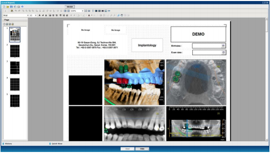
Expanded [X-Report] window
Scale options for the image boxes can again be edited in this window. Use the to scale an image to [Real Size], or to scale the whole image to fit the window. Click on the icon and drag up or down on an image to zoom in and out. To pan an image, use the icon provided.
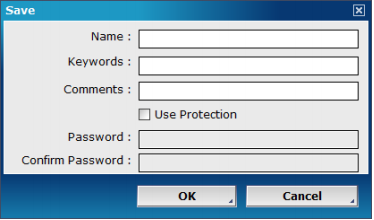
Save X-Report
Click save and provide details such as name, keywords, comments and whether to use password protection, as shown in Fig. 123. Saved reports can be accessed from DBM under the patient series, shown as XFM data. Double click and open with X-Report to edit.
Save X-Report
Export X-Report
Reports can then be exported as either PPT, JPG, HTM, or PDF data.
Simply click , select file destination along with file format, input name and press export .
Print X-Report
Select print to print report.
X-Report Template Designer
Design your very own custom templates using X-Report Template Designer. Create specialized report styles for each patient’s needs and increase the efficiency of writing a report. To start X-Report Template Designer in Windows, press [Start] → [Al Programs] → [OnDemand3DDental] → [X-Report Template Designer] as shown below.
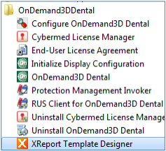
Run X-Report Template Designer from the Start menu
X-Report Template Designer provides functions to create and manage report templates. Based on XML, X-Report makes it possible to bind data elements such as patient ID, name, sex and etc. to a control. Please read further for more information.
Layout
X-Report Template Designer is composed of a number of menu selections on both sides of the screen, an editing toolbar at the top, and a simple and straightforward look.
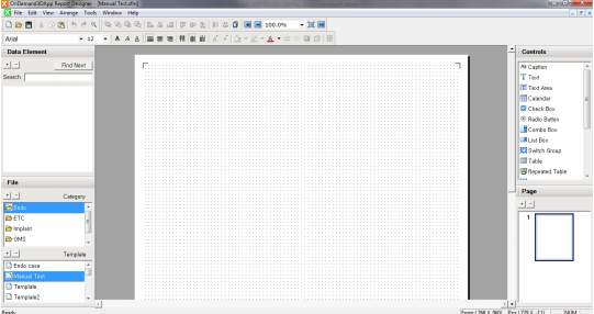
[OnDemand3D Report Designer] layout
Tools
The tools included in X-Report Template Designer are similar to tools found on general word processors.
![]()
Editing toolbar provided on X-Report Template Designer
Create new template. Press or go to [File] → [New], input file name, paper size and paper orientation information in the [New File] dialog and users will see a screen similar to Fig. 125. Another way to create a new file is to click the [+] icon in the ‘Template’ section at the bottom left corner of the screen.
Users can manage their report templates using the [+] and [-] icons provided in the ‘File’, ‘Data Element’ and ‘Page’ sections. Press [+] to add, and press [-] to delete. Add any number of categories and templates to the template database and organize them for easier access.
Save template. To save the current template, click in the toolbar or select [Save] from the [File] menu.
Load template. Double click on a template in the ‘File’ section or click from the toolbar.
Adding Controls
After a new template has been added and opened, users can simply drag and drop controls from the [Controls] section on the upper right side of the screen
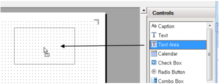
Drag and drop controls onto template
After the controls are dragged in, resize and re-position as needed. Users are provided with a grid for easier positioning, which will not be visible on the actual report template. To configure grid settings, go to the [View] menu and set preferences
Right-click on any control or double-click and choose [Properties] to change settings such as fill and border color, text style or effects such as shadow and 3D.
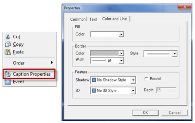
[Properties] window
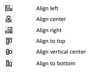
Drag to position and align controls or use the alignment tools provided on the upper toolbar.

Data Element Binding
Combine controls with data elements such as the patient ID, name, sex and even images. If a control is bound, the corresponding information will be automatically entered from the DICOM data when the user writes a report.
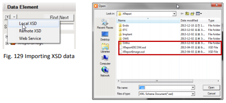
Loading Data Elements. Data elements are saved in XSD file format. Click the [+] icon from the [Data Element] section on the upper left side of the screen, choose [Local XSD] and open the [XReportDICOM.xsd] file. This file contains the header information of DICOM data such as the patient ID, name and etc.
Binding Data Elements. Drag a data element from the menu and drop into a control on the report. The two will be automatically bound. Bound controls will have a small comment on the upper right corner, such as , while controls that have not been bound will have a sign indicating .
Controls
Create custom templates using the controls provided and bind them to data elements for easier and simpler reporting.
Caption. Create a box to display text labels. Click inside the box and enter text. Right-click and choose [Properties] or double-click to change settings.
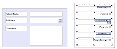
Text. Create a box for inputting single-line text. To set a default text to display, go to the [Properties] menu and in the [Data and Option] tab, enter the default text to display. shows two text boxes. One showing a default value of [Name:] while the other one has been bound to the data element [PatientName].
Text Area. Create a multi-line text box.
Calendar. Create a pop-up style calendar box. Calendar boxes can also be bound to the [PatientBirthDate] data element.
Check Box. A check box may be used to answer a yes or no value or for a basic checklist as shown below. Drag in check boxes and click to edit the labels.
Any number of items can be selected in a checklist, and the user can also set it up so that some of the check boxes are checked in default with the [Data and Options] tab in [Properties].
Radio Button. Create a group of choices where only one item can be selected. Users will be prompted to put in their radio button values in the [Insert Radio Button]
dialog, as shown Fig. 135. Use the [Add] button to add in new values and [Modify], [Remove] or [Move up] if necessary. Select the default value as well, and as shown in Fig. 135, it will be set as the first choice.
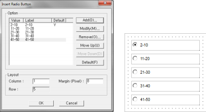
[Insert Radio Button] dialog
Combo Box. Create a [Combo Box] control that can be used to present a list of options in the form of a drop-down menu.
List Box. Create a [List Box] to present a scrollable list of text items. To insert items, double click and go to the [Data and Option] tab.
Switch Group. Add a control that allows for switching between tabs. Enter a different control or different menu options for each tab
Table. Create a table and click to enter text. Each cell can be bound to a data element. Dragging adata element folder of choice into the report and choosing [Table] will automatically create a table with the bound data elements
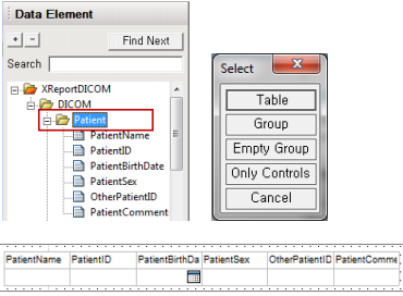
Creating a data element [Table]
Repeated Table. Create a table with rows that can be repeatedly added onto the table along with the information contained. Drag the control onto the report and follow the same steps as with a [Table]. Go to [Properties] and on the [Data and Option] tab, choose the number of rows to be ‘repeatable’.
[Repeated Tables] on the actual report will include a small beside a table row. Click on it and choose where to insert the additional row.
Repeated Groups. Create a group for repeated table elements as shown below.
Picture. Create a picture box to be used for company logos, patient photos and etc.
Image. Create an image box to display an image.
Multiple Image. Create an image box to display multiple images from OnDemand3D™ by inserting different images into each cell.
To change the layout of an image box, use the in the upper toolbar.
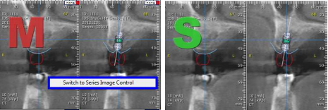
Series Image. Create an image box to display a series of images from OnDemand3D™ Dental. With this, the user would only have to drag the first image in, and the others will fill up automatically.
To switch from [Multiple Image] control to [Series Image] control and vice versa, simply right click on the image and clock [Switch to Series Image Control] as shown below.
Group. Create a group box to group together several controls, as shown in Fig. 146. Users can also drag a data element folder into the report and select [Group], which will automatically create a group of controls already bound with data elements.
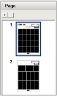
Managing Pages
Add or delete pages using the [+] and [-] icons provided and drag and drop pages to change the order.
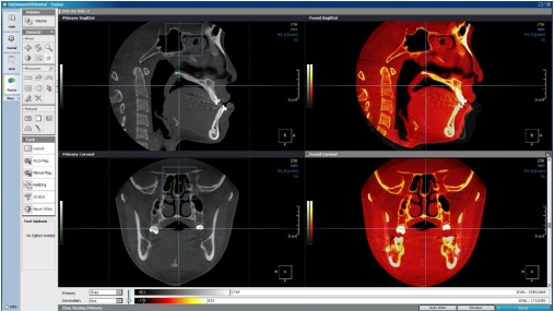
Fusion (Optional)
Fusion is a visualization tool that utilizes an advanced registration technique to superimpose or stitch image data regardless of modalities such as CT, MRI and PET. The Fusion layout consists of MPR images of the Primary, Secondary and Fused patient data. Images reconstructed with Fusion can then be resliced as new DICOM data.
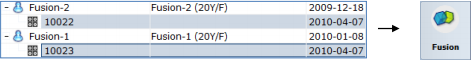
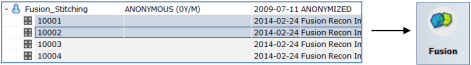
To launch, select two series of data using the [CTRL] or [Shift] keys
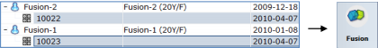
Select two series at once
Click the [Fusion] icon on the module bar, once again select the two sets of data from the [Loading Options] dialog and press [OK]
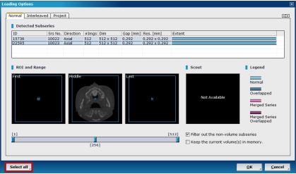
Reselect both data from [Loading Options] using either [Shift] or [Select All] (shown in red)
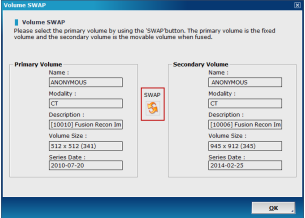
Swap primary and secondary volumes if necessary using the icon.
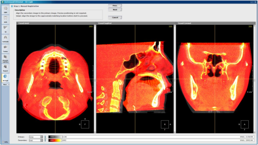
Please note that only the secondary volume can be manipulated and aligned to the primary volume.
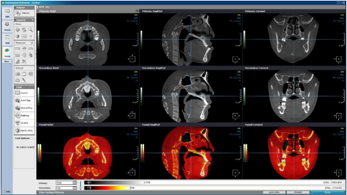
Layout
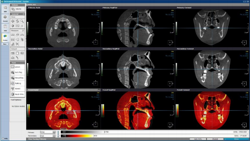
The Fusion module default layout consists of primary (top), secondary (middle) and fused MPR images (bottom)
At the bottom of the layout, users will see a fine tuning bar for both primary and secondary data.
![]()
Configure color and intensity settings for the primary and secondary MPR images
Color settings can also be accessed by clicking the color bar shown above in red, provided along the left margin of each MPR pane
Change pane orientation settings by clicking on the upper left corner of any pane
Task Tools
Users will be provided with the following tools on Fusion:
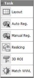
Fusion task tools
Layout. The default layout of Fusion includes primary MPR images at the top, secondary MPR images in the middle and fused images at the very bottom. To change the layout, click on the tool and select a display of choice from the [Choose Layout] window
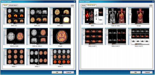
Choose desired layout from either the [Head] or [Whole Body] tab
Auto Registration. The automatically registers volume data using voxel information. The technology behind Fusion, known as MI or Mutual Information, calculates the statistical dependence between two volumes, the intensity and correlation values of entropy and compares the difference in the entropy of the sum of individual images and the joint entropy of combined images to fuse data together. See next sections on superimposition and stitching for instructions on the correct use of this tool along with the workflow involved.
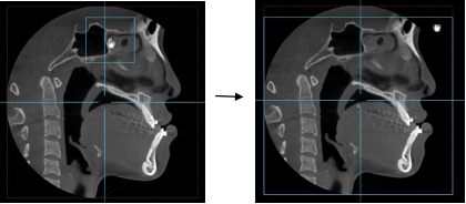
Manual Registration. If images fail to match due to a wide difference between the positions of the two images or if automatic registration is taking too long, users can match images manually by clicking . The secondary image can be manipulated, while the primary image position remains fixed.
Click and drag to re-position and use mouse-wheel to rotate the image.
Click and drag to reposition (left); Use mouse-wheel to slightly rotate the image (right)
Reslicing. The fused set of data can be converted into DICOM format and saved in the user’s database or remote server. To do this, choose from [Task Tools] and the following menu will pop up.
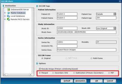
Reslice data using the [DICOM Store] dialog
Users will be able to input different patient, study or series information in the fields provided. To anonymize the data, press and the DICOM will be automatically renamed as ‘Anonymous’. In the [DICOM Frame] section, choose whether to keep the original frame settings or whether to convert to either split-frame or multi-frame.
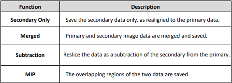
The [Options] menu section presents the user with the following choices to reslice the fused DICOM data:
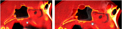
3D ROI. Select and an ellipsoid outline overlay in blue will appear on the MPR images, while the statistical data related to the pixel values inside of the ellipsoid will be displayed in the [3D ROI Information] window. While this tool is being used, the maximum value of the current secondary volume and the slider controller for adjusting the threshold can be accessed at the top right
corner of the screen.
Use the exterior control points to drag in/out and resize the ellipsoid and the point in the center to reposition
 Adjust region of
interest by resizing and
repositioning
Match WWL
Once primary and secondary volumes aligned using Manual/Auto Registration, select to automatically match the secondary volume WWL to the primary volume WWL. To save secondary volume with the adjusted WWL settings, save the volume as a new DICOM with the help of [Reslicing] tool and make sure [Rescale Image (Primary windowing based)] and [Secondary Only] are checked in the [Options], as shown in Fig. 158, before pressing [OK]
Superimposition
Superimpose post-operation and pre-operation patient data using Fusion’s registration technology to draw comparisons for post-operation analysis. The following is a step by step guide on how this can be achieved.
Step 1: Launch both data from DBM using the [Ctrl] or [Shift] keys to select both as shown below. Reselect the data from the [Loading Options] dialog.
Select two series at once
Fusion module layout
Step 2: Change layout, color and windowing settings to suit needs.
Step 3: Start superimposition.
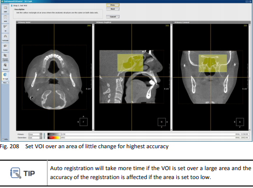
For bigger sized data, make sure to draw a volume of interest (VOI) overlay over the area that involves as little anatomic change as possible for the patient’s pre-operation and post-operation data. This will ensure the highest accuracy for the superimposition.
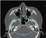
Click from [View Tools] and adjust the volume of interest by dragging in the sides as shown below.
Drag in each side on the MPR panes provided and use the small square in the middle of the [VOI] overlay to reposition if necessary.
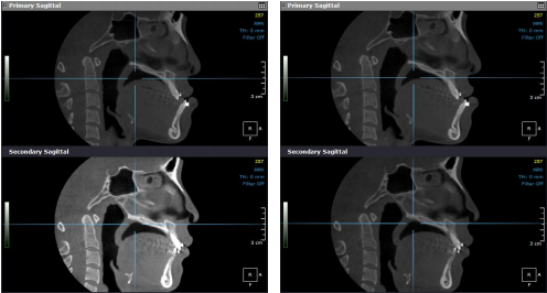
Step 4: Click to start automatic registration.
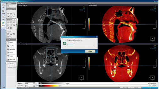
Registering the two volumes
After successful superimposition
Click again to hide the [VOI] outline.
Step 5: If necessary, proceed with manual registration by clicking .
Final step: Press to reslice data with new patient information and select options to save the data as either [Merged], [Subtraction], [MIP] or [Secondary Only]
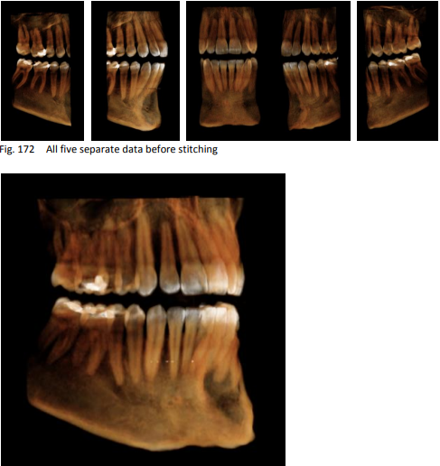
Stitching
The Fusion module has the capability to stitch together small FOV data using the same advanced technology used for superimposition. To stitch together more than two sets of data, simply stitch the
data two at a time and reslice them as [Merged].
The following is a step by step guide on how to stitch a number of small FOV data
Step 1: To start, select the data to stitch from DBM as shown below and select both data from the [Loading Options] dialog again.
Step 2: Change layout, color and windowing settings to suit needs.
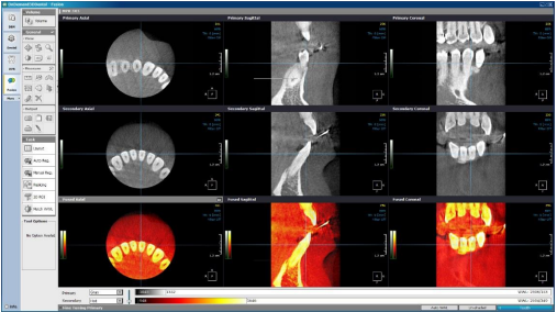
[Layout] was changed to [3 x 3], and windowing preferences were set
Step 3: Click on and first roughly align the secondary data to the primary. Click and drag to move and use mouse-wheel to rotate secondary data.

The secondary image is roughly aligned to the primary
Step 4: Press auto reg to proceed with automatic registration
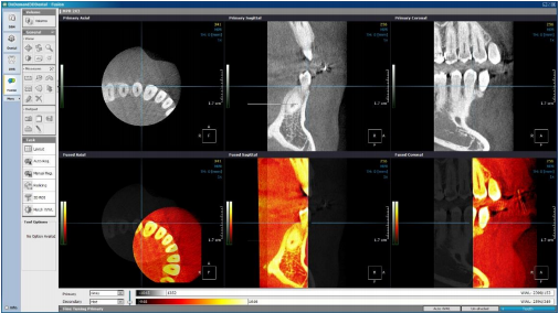
The two data are automatically aligned using voxel information
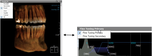
(Left) Check results in 3D view by clicking on the upper left corner of a pane and selecting [3D]; the [Fine Tuning] settings of both the primary and secondary can be set as shown above (right)
There will be no obvious outlines on the 3D volume after merging is complete.
Step 5: Use reslising the tool to reslice data using [Merged] option.
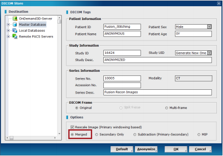
Input new DICOM tag information if necessary, select [Merged] and press [OK]
Step 6: Stitch the remaining data using the method prescribed above and merge.
Final results: Open up the final stitched DICOM from DBM.
3D Ceph (Optional)
3D Ceph calculates the relative functions between points, lines, and planes in a three-dimensional setting to provide more precise and accurate values. The user can define the points, lines, planes and
functions in accordance to their needs. The user can also do a superimposition of two sets of image data, such as pre and post-operation data to analyze results as well as use a 2D photo for 3D volume mapping or generate a 2D X-ray for patient consultation. For workflow and instruction related to superimposition on 3D Ceph, please refer to the last part of this section
Layout
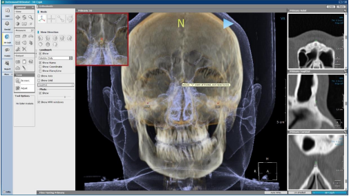
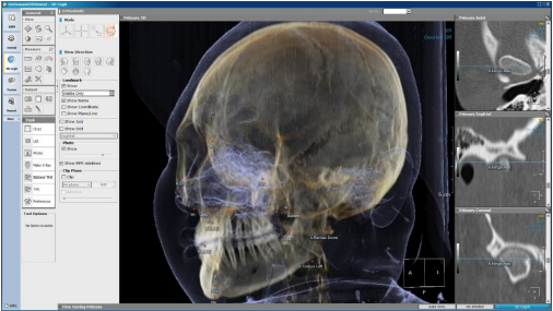
The 3D Ceph layout consists of MPR and 3D views along with an additional menu (shown in red below) which includes tools such as [Mode] and [View Direction].

3D Ceph layout
Workflow
The workflow of the 3D Ceph module starts with loading patient data and setting the orientation axis using [Reorientation] mode.
See chart below for the needed workflow.
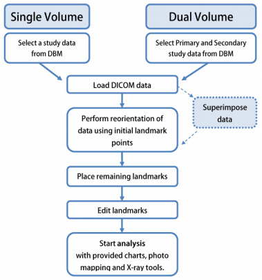
3D Ceph workflow chart
The four modes provided on 3D Ceph can be seen in their appropriate order of usag
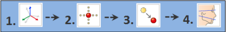
From left to right: [Reorientation], [Tracing], [Edit] and [Display].
Single Volume
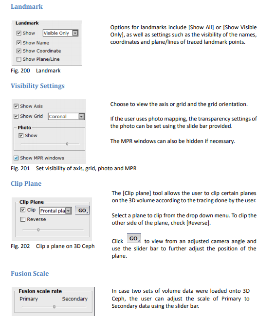
The following is a representation of the user’s workflow when using a single volume for cephalometric analysis. workflow related to using two volumes of data.
Reorientation
Using this tool, set the orientation axis of the 3D volume. Click on and from [Task Tools]. Select preferred reorientation method from the [Select Reorientation Method] dialog.

According to preferred reorientation method, place necessary landmark points in their proper location by referring to the description shown beneath the mouse cursor. Click to place the landmark, and if necessary, reposition using the green [x] provided on the MPR panes for precision
Place landmark points with the help of zoom image (highlighted in red) and MPR images (highlighted in white)

The landmark can also be adjusted using the green [x] shown on the MPR images
After placing a landmark, click on the blue arrow to proceed to the next landmark point. When finished, the auto reorientation process will progress.
If needed, adjust the orientation axis manually, using the [Adjust orientation] dialog shown
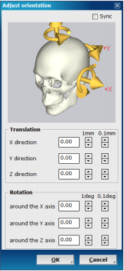
[Adjust orientation] dialog
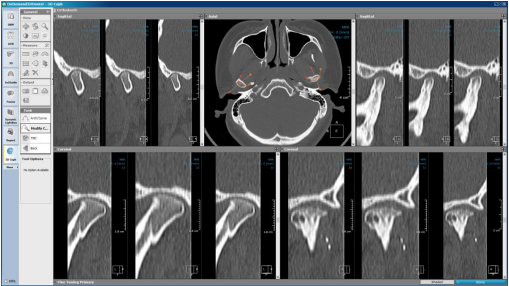
Tracing
After orientation, click [OK] when prompted to continue onto tracing or simply click to place remaining landmarks using the 3D and MPR images provided. Use the and buttons at the top right corner of the layout if needed.
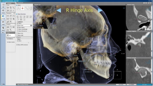
Tracing the right hinge axis
Go to for a full list of landmark points, and erase points whenever necessary.
Edit
To start editing landmark positions for higher accuracy, press and use the menu provided, which is sorted in alphabetical order, to go over points one by one. Simply clicking on a landmark to edit will also work. Red landmark points will appear yellow when in editing mode.
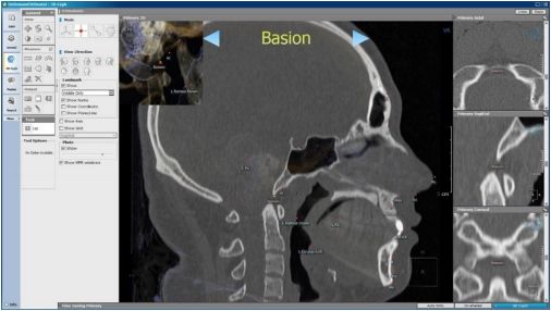
Display
The mode shows the defined landmarks, lines and planes.
3D Ceph task tools can be accessed from [Display] mode
When initial tracing is done, users can use the [Tools] section for analysis.
Tools
The following are task tools provided in 3D Ceph.
Chart. The tool displays the analysis values calculated using the landmark points. OnDemand3D™ offers ‘Dr.Cho’s Analysis’ by default. To add or remove analysis methods
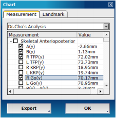
Analysis values in mm
Check or uncheck analysis values to view on the 3D volume.
Click to export analysis results as either a text file or an excel spreadsheet.
List. The tool displays landmark points and their appropriate coordinates.
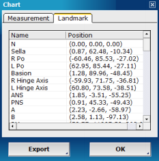
Landmark coordinates can also be exported
Photo. Allows users to map a patient photograph to the 3D volume. Click and the [Extract Surface] dialog should appear. Set the ROI (region of interest) on the axial image shown using the blue outline. Adjust the HU (Hounsfield unit) threshold values using the bar provided until the area highlighted pink covers the patient’s skin surface. Scroll the axial pane to make sure all areas are covered.
Click generate to render a surface area model of the patient. After the 3D image is generated, make adjustments if necessary and press [OK] to continue onto the next stage.
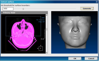
Adjust HU threshold for a surface model
Direct path to the patient’s photo and place the two orange circles directly over the patient’s pupils.
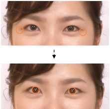
Click next.
Pick at least four corresponding points on the photo and the surface model. When a point is chosen on either data, the area is enlarged and shown in the [Image Zoom] pane. The edges of the eyes, the mouth, or the center of the nose are recommended for the best mapping results.
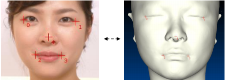
Place corresponding points to map photo onto patient data
After placing at least four points, click next .
In the next stage use the or tools provided to remove unnecessary areas or any distortion.

Verify the final image and click [OK] to finish mapping and return to the main window.
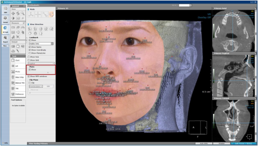
The opacity levels and visibility of the photo can be adjusted using the slide bar provided (highlighted in red)
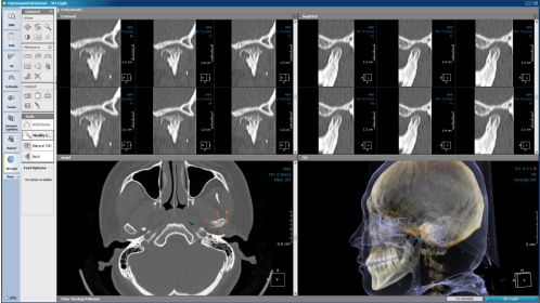
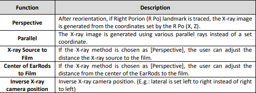
Make X-Ray. First, set preferences for X-ray image generation using the [Preference] menu from [Task Tools]
After preferences have been set, click . After the [Select Position] dialog appears, choose desired X-ray orientation and click [OK] to start generating the X-ray image. The four orientations provided are [Lateral], [Frontal], [SMV], and [Panoramic].
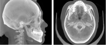
Lateral and SMV X-ray images generated using 3D Ceph
For panoramic X-rays, a [Draw Arch] dialog appears. First, set the threshold values for the panorama and draw an arch on the axial pane provided. Set the ROI in the sagittal pane and press [OK] after
verifying.
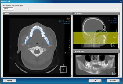
Generate a panoramic X-ray image by drawing an arch
In X-ray mode, users are able to generate the soft tissue profilography as well as the polygonal chart of the patient. Use the along the top right corner of the screen to show or hide landmark points on the 2D image. Use the in the top right corner of the screen or filter option in the top right corner of the [XRay Image] pane to adjust filter of the 2D image.
2D Chart. Click on to view a polygonal chart based on different analysis methods. Select preferred analysis method from the drop down menu provided. The available analysis methods available are as follows: COGS, Downs, Jarabak, Kim, McNamara, Ricketts and Steiner.
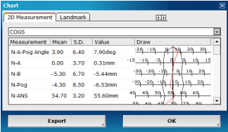
Select a preferred analysis method and [Export] if necessary
Export. The generated X-ray image can then be exported using the task tool provided. The allowed formats are JPEG and DICOM.
Settings. Click to view the [Analysis Management] dialog, shown below
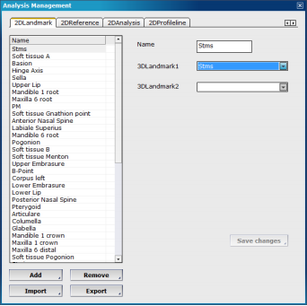
2D analysis settings
The four tabs included are [2DLandmark], [2DReference], [2DAnalysis] and [2DProfileline].
Names of landmarks, references, analyses and profileline are listed with their corresponding details and settings. To make changes to existing values, simply select a different option and click save changes
Other options:
Bilateral TMJ. As its name suggests, this view generates a bilateral view of the patient’s TMJ cross sections. Click on and use the to draw out a polygonal shape over the patient’s condyle. The TMJ views will be generated according to the arch/curve drawn, so use the to modify the arch/curve if necessary.
Bilateral TMJ layout
TMJ. [TMJ] creates a singular view of one condyle, unlike [Bilateral TMJ].
TMJ view on 3D Ceph
Preference. Click from [Task Tools] to set options for X-ray generation.

3D Ceph preferences
Landmark DB. Click on Landmark DB at the bottom left corner of the [Preference] menu to define landmarks, references and analysis methods in the user’s library, as well as their relations, such as distance and angle.
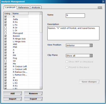
3D landmarks, references, and analyses
Click and drag landmarks to change order of appearance or uncheck to exclude. Changes can be made to the description, view position and clip plane settings of each landmark, and saved using the button provided.
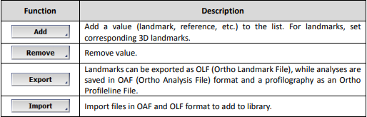
Similarly to the 2D analysis settings, users can add their own landmark points, references and analysis methods using the add button or remove unwanted ones using remove . The information needed to add a landmark, reference or analysis method differs.
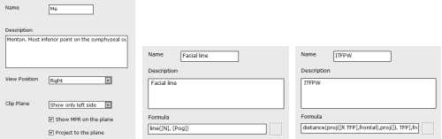
Landmarks (left) require view position and clip plane settings, while references (middle), similarly to analyses (right) require a description and a formula to match.
For landmarks that are seen better on MPR panes, the software shows an MPR overlay on top of the 3D volume. When inputting custom landmarks, the user can use the [View Position] and [Clip Plane] (see Fig. 180) settings to set the corresponding landmarks’ ideal visualization settings
Users can also use the import and export buttons import and export landmark point, reference and analysis information as OLF or OAF data.
Additional Tools
View Direction
![]()
Select preferred viewing direction
Dual Volume
3D Ceph can be used to superimpose two sets of data and perform cephalometric tracing. The following is the workflow associated with loading two volumes of data onto 3D Ceph.
First, select two sets of data from DBM.

Select two sets of data using the [Ctrl] key
In the [Loading Options] window, make sure to reselect both data and press [OK].

The software will load the primary data first, allowing the user to switch between primary and secondary using the menu provided on the top right corner. After superimposition, users will also be able to switch to Fused mode.
Press superimposition to launch the Fusion wizard, as shown below.
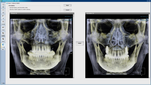
Set which data is Primary and which is Secondary; SWAP if needed
Click next to proceed with manual registration.
Use mouse to align; drag or scroll to rotate
Drag Secondary data and use mouse scroll to rotate to align the two volumes.
Click next again and set the VOI (volume of interest) of the data. The VOI is needed for automatic registration. Adjust the size of VOI box using the axial, sagittal and coronal panes provided. It is recommended to place the VOI in an area of little change, such as the Nasion or Sella.

Automatically registered data
Click next to proceed with automatic registration and press OK to finish.
Users can also go over previous steps with the PREV button if necessary.

MPR 2×3 view is generated
The following task tools are available:
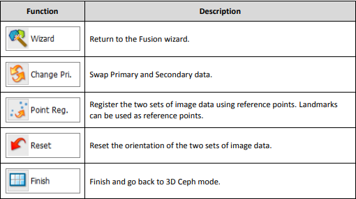
Click [Finish] to go return to the 3D Ceph main layout.
To trace, users can first trace landmarks on the Primary data and click copy from from [Task Tools] to copy them onto the Secondary data.
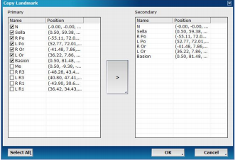
To trace on the Secondary data, simply use the on the top right corner of the layout and select [Secondary]. Landmarks on the Secondary data can also be copied onto the Primary data.
After the user has reached the mode, the [Current Volume] can be changed to [Fused] to see superimposed data.
X-Image (Optional)
X-image makes patient data integration as simple as it gets. Now
both 2D and 3D data can be stored on OnDemand3D™ and easily
separated and organized according to data modality and format.
X-image supports DICOM, BMP, JPG and TIF. Images can also be
directly acquired and organized with respect to modality, such as
‘Panorama’, ‘Cephalometric’ and ‘Intraoral’.
To access X-Image, select patient from [Master Database] and click X on the icon displayed in the [Thumbnail] section of the DBM module.
Layout
The default layout of X-image consists of nine sections for organizing patient data.
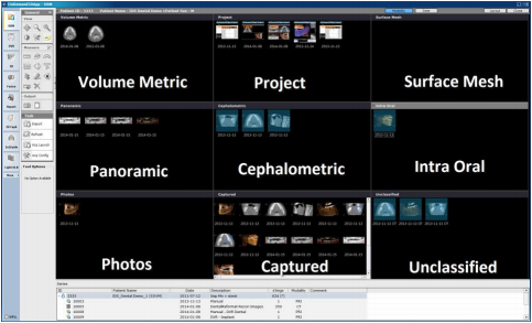
Each section shown labeled in white
Click on at the top right corner to edit sections to include and exclude on X-Image.
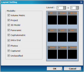
Edit X-Image [Modality] layout
The user can choose between the two layout options by clicking either or from the top toolbar.
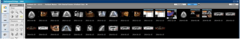
The [Date] layout organizes patient data by either ascending or descending dates
Tools
The X-Image module has three additional tools in the general section, and four task tools available for use.

Import. Use the tool for additional patient data such as image (DCM, JPG, BMP, TIF) and surface mesh (STL, PLY, PCM) data.
When data is imported, there will be a small dialog asking the user to input patient information and data type, as shown below.
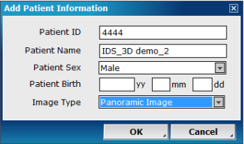
Input relevant information and press [OK] to finish import command
Acq Launch. After a path to the Launcher program has been set up using the [Acquisition Configuration] tool, simply click to launch the program for data acquisition.
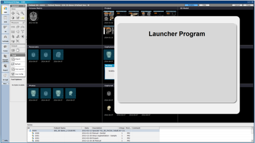
OnDemand3D™ launches the program to jumpstart acquisition
Acquisiton Configuration
Configure OnDemand3D™ to directly acquire from imaging devices using the tool. There are two main protocols to choose from.
TWAIN. X-Image makes use of TWAIN, an “applications programming interface (API) and communications protocol that regulates communication between software and digital imaging devices” such as image scanning devices.
The configuration for this protocol is shown in the image below. Detected TWAIN protocol devices will be listed in the [Device Information] section, and the user will be able to allocate devices to the appropriate sections using the [Select Device] menu.
Input width and height calibration info for the device if needed.
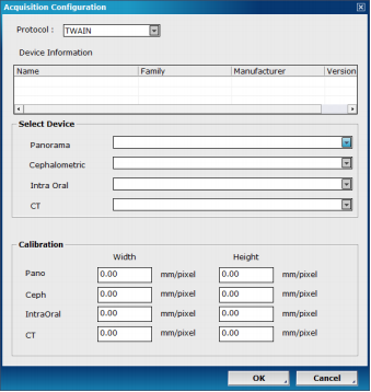
Fill in information to set up
Launch. Another option is to use [Launch] to integrate OnDemand3D™ with a launcher. Choose the equipment manufacturer and set up the launch file path. Then set up image path designations.
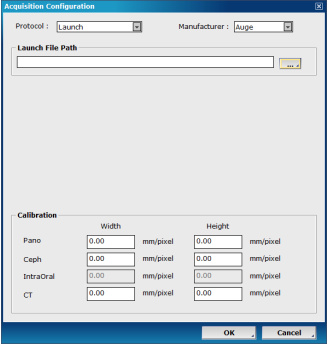
Set up launch file path
When the launcher program processes images and saves them in a designated folder, OnDemand3™ acquires them using the paths set up by the user.
Image Options. View imported images on OnDemand3D™ and apply filters and rotate for convenient viewing.

Image options location and available menus
3D Volume Options. Double click on surface mesh data to open up the [Surface Mesh Viewer] on X-Image.
All general tools and functions such as rotate, pan, and zoom will work on the [Surface Mesh Viewer] along with measurement tools and output tools such as [X-Report] and [Capture].

Sample text and arrow annotations as shown on OnDemand3D™ [Surface Mesh Viewer]