
The Assembly of components
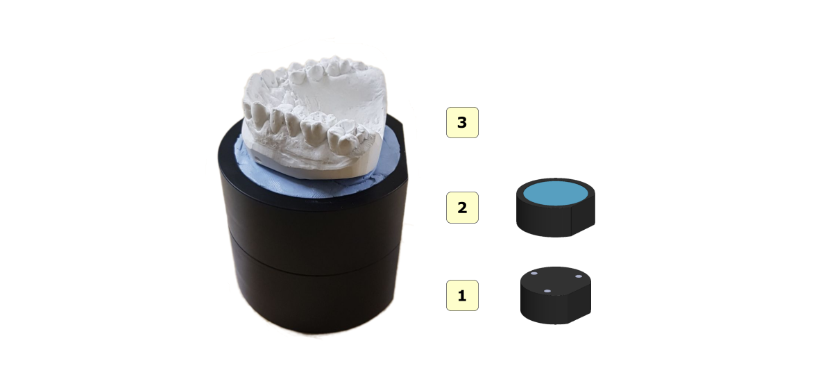
Assembly of the calibration kit
See the figure below for instructions on how to assemble the calibration kit after removing it from the packaging.
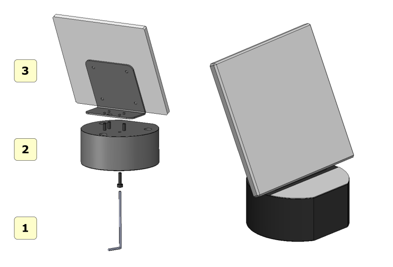
1 hex key;
2 plates;;
3 calibration plate;
Simply screw in the 4 supplied screws to connect the plate to the calibration plate. Be careful not to scratch or stain the calibration plate. It is recommended to handle the plate with gloves, so as not to stain it or leave fingerprints on it.
WARNING
store the calibration kit in a place protected from direct light and moisture;
do not clean with solvents or acids, and use only a dry cloth;
scratches or dirt on the calibration plate can compromise the calibration of the scanner;
handle cloth gloves carefully to avoid leaving fingerprints or dirt on the calibration plate.;
Assembling the impression holder
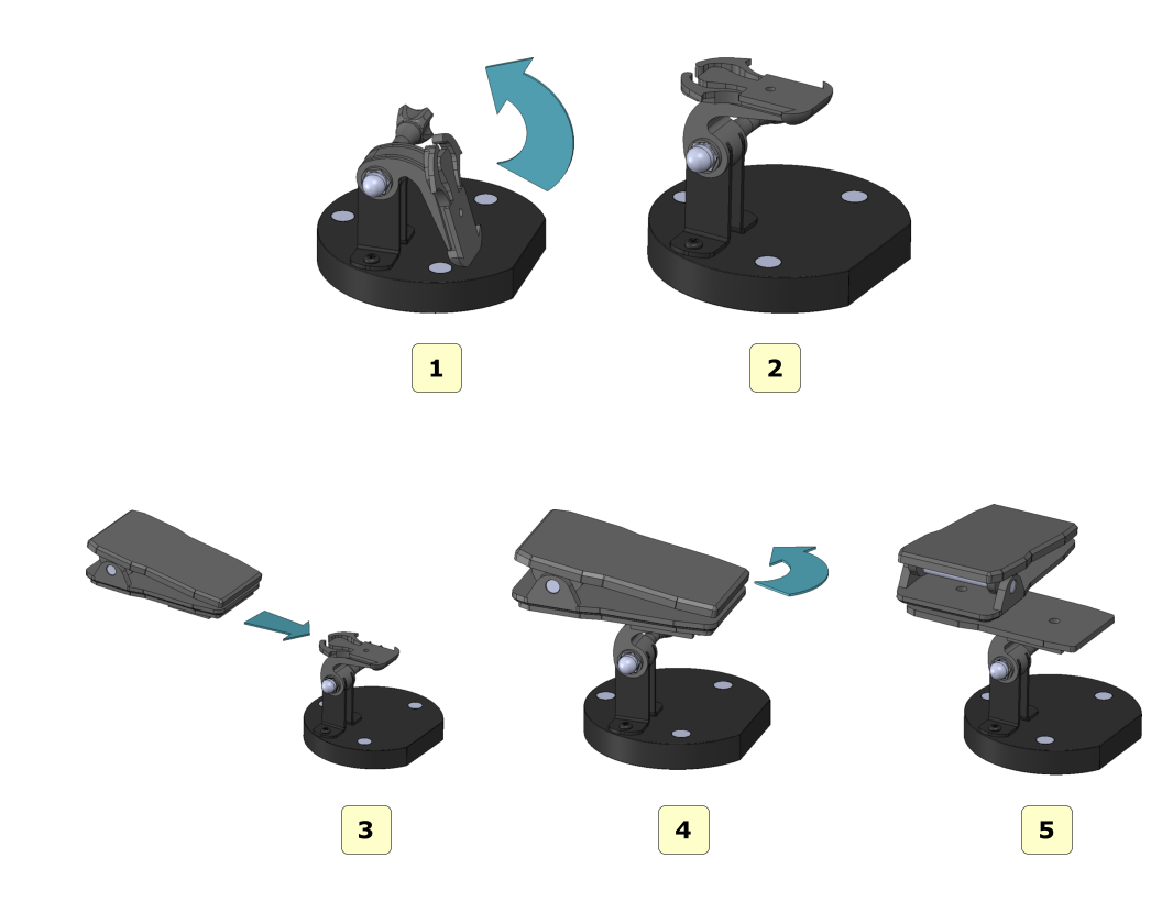
Follow the steps shown in the figure to properly assemble the impression plate after removing it from the package.
Tablets to scan
The figure below shows all the scanning plates that come with the MDS 500 scanner::
1 interface plate;
2 plate for arc model;
3 die plate;
4 impression plate;
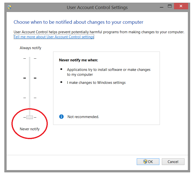
UAC-User Account Control
To avoid difficulties and limitations in using the Software, you need to set the UAC-User Account Control slider to a minimum value, as shown in the figure below.
To enter the settings window: Control Panel-> User Account-> Change User Account settings. (Control panel-> User Account-> Change Settings User Account Control)
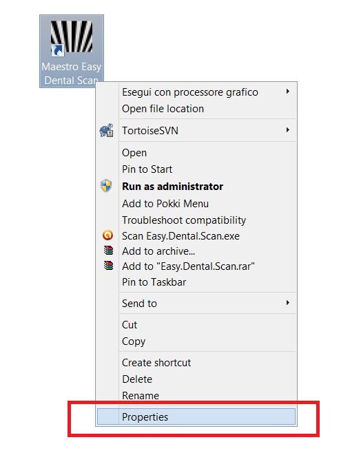
Administrator Rights
To run the Software, you must set the administrator rights correctly.
Follow the instructions as shown in the pictures below.
Right – click on the software icon to launch the context menu and select record properties.
Follow the steps as shown in the sequence from 1 to 4.
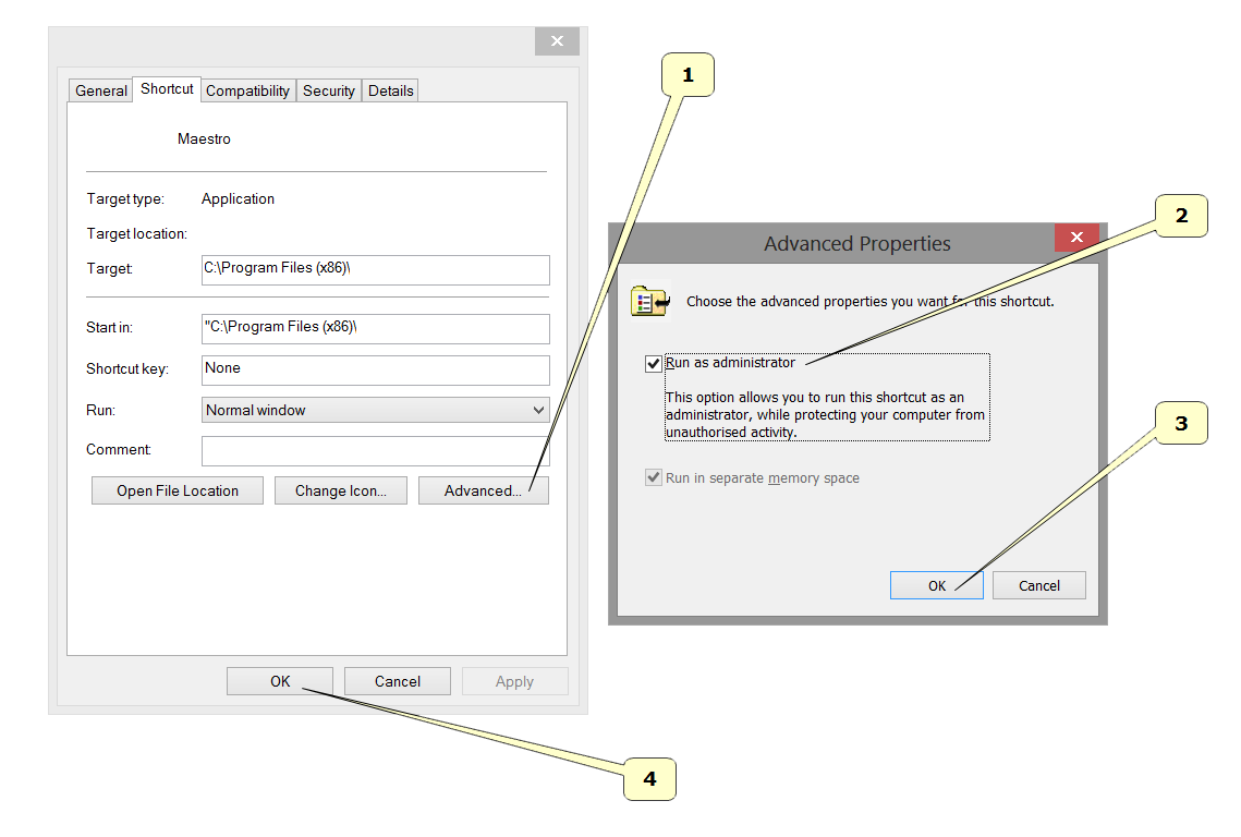
Click the Advanced button.
Select Run as Administrator.
Press the Ok button.
Press the Ok button.
User Interface
The figure below shows the structure of the user interface.
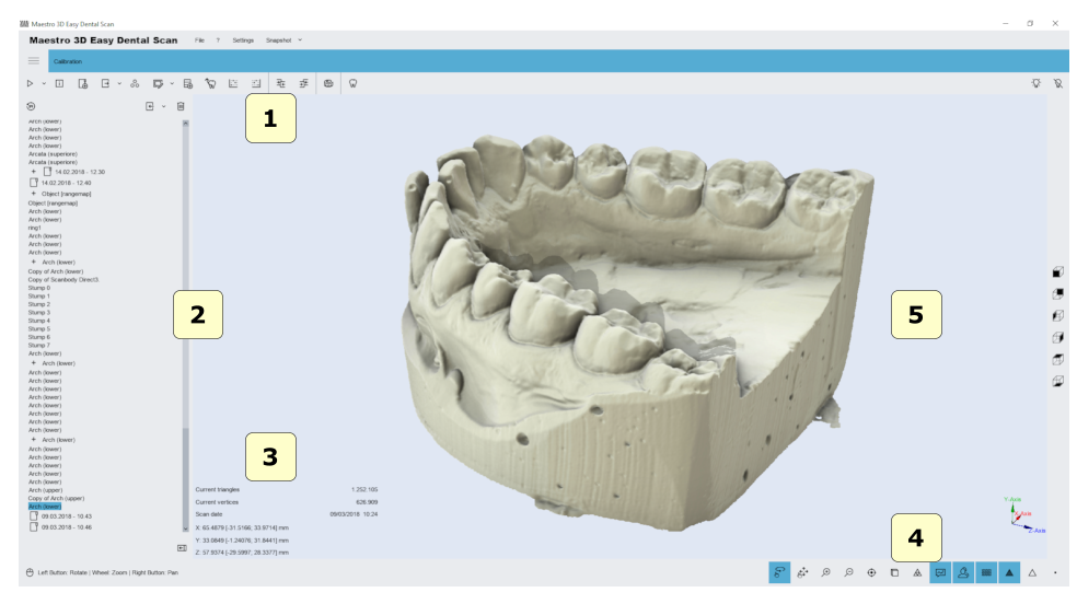
1) the Main toolbar.
2) The area of trees.
3) Information zone.
4) the bottom area.
5) Visualization \ Editing area.
The main toolbar
The main toolbar provides access to all the features of the Easy Dental Scan software.
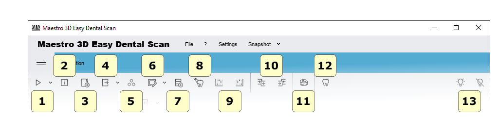
1) New Scan-start a new scan or define a new scan strategy.
2) Scanner Status-activates a window that monitors the status of the hardware scanner.
3) New Group-adds a new group to the tree. You can move tree elements inside / outside the group by dragging the mouse.
4) Export-Export the selected element on the Z or Y axis. You can export to an open STL or PLY file.
5) Postprocess (conversion of scanned data into a 3D model) – the function is activated if the item is selected, and not subjected to subsequent processing. This operation may take several minutes to convert the scanned data from the scanner to a triangular geometry.
6) Editing a filter to Edit the selected elements. This is useful for removing artifacts due to scanning, for removing scanned putty, for performing hole filling, thinning, 2D \ 3D selection editing, etc
. Editing with a 2D rectangle
Editing with a 3D polyline
Editing with 2D selection
Filling voids
Pruning
7) Import a scanbody from library.
8) automatic stamp alignment procedure.
9) set the selected element as fixed or floating in the manual alignment procedure.
10) Comparison.
11) Measurements:
the point of measurement.
the angular measurements.
12) CAD-send selected elements to the design software.
13) Status of the projector.
Turn on.
Switch off.
The bottom toolbar
The bottom toolbar is an area of the screen that contains a progress bar that is displayed and updated each time the program is calculated, as well as controls for changing the visual settings of the visualization / editing area.
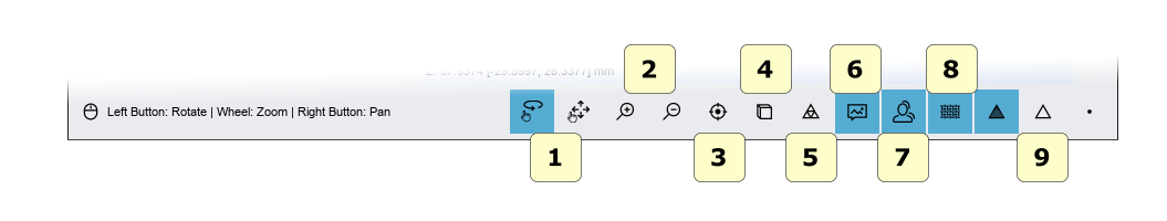
1) Touch screen mode (rotate / pan).
2) zoom in [PgDown key] / zoom in [PgUp key].
3) Reset the trackball [R key].
4) Parallel projection [O key], perspective projection [P key].
5) Smooth shading [S key], flat shading [F key].
6) photorealistic visualization.
7) shadow, (available if photorealistic rendering is enabled).
8) texture color, (real object color).
9) show / hide triangles, edges [E key], vertices [V key].
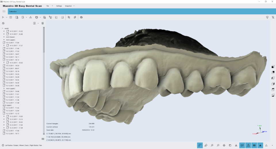
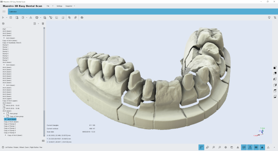
Visualization / editing area and information area
The visualization / editing area is the area of the window where models are rendered and all editing operations are performed.
In the visualization area, you can view models, edit and measure the distance between different points.
To view the models displayed in the visualization / editing area, the camera settings (position, zoom, and rotation) can be adjusted using a tool called trackball.
Trackball is very easy to use. Just use the left mouse button to rotate around the model, the mouse wheel to zoom in / out, and the right mouse button to move (pan) the camera.
The information area of the screen displays information related to the
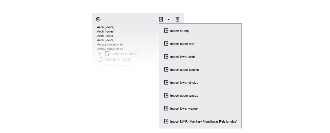
Tree Area
The tree area contains all of the scanned models. Using groups allows you to maintain the order of scanned models. To select a model from the tree area, simply click on it with the left mouse button. The selected models will be displayed in the visualization area. To select more models, press and hold CTRL \ SHIFT.
Each of these elements corresponds to a set of operations available through the enabled icons on the main toolbar. This allows the user to access the main functions of the software.
Once you have access to the drop-down menu, as shown in the following figure, you can import an STL file into the tree.
Targets
Some examples of targets:
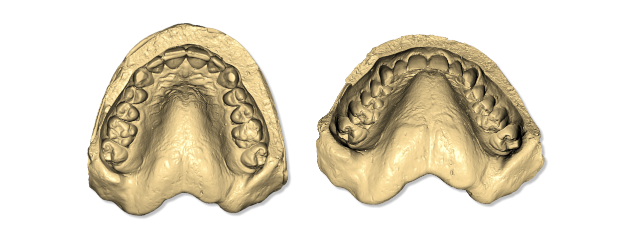
Relationship of the upper and lower jaw

Upper-Lower Jaw
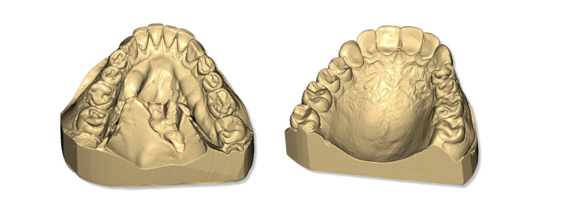
Other examples of a dental arch
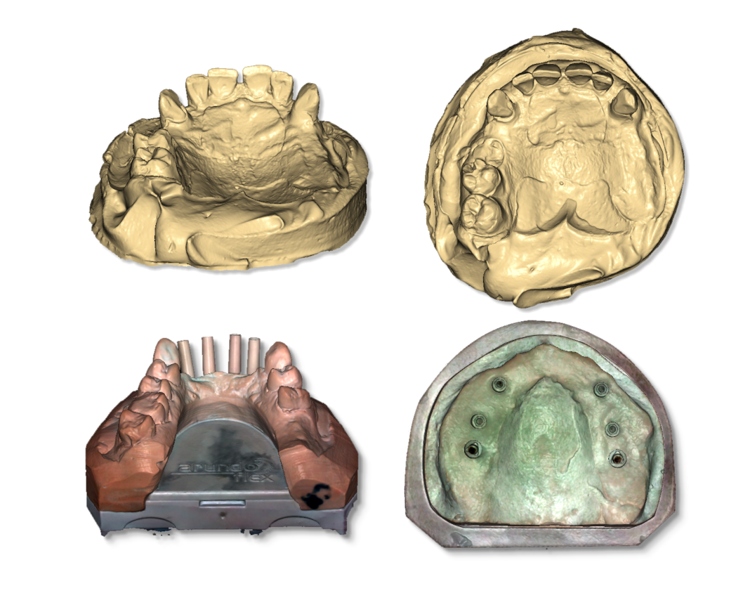
Impressions
Stamps
Correct location of objects
Arc or MMR
The following images show the correct position of the models on the turntable. The picture below shows the arch correctly positioned on the turntable. The arch should be placed in the center of the turntable, supported by putty or any other adhesive that keeps it well attached to the table.
The arch should be parallel to the surface and should not be tilted.
1 interface plate;
2 plate for the model;
3 objects to scan, arch or mandibular relations of the lower jaw (MMR);
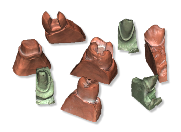
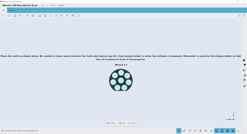
Stamps
Up to 8 stamps can be placed on the scanner’s turntable at the same time.
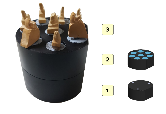
1 interface plate;;
2 die plate;
3 stamps;
After the scanning process, the software automatically recognizes and separates individual stamps, adding an element in the tree area for each received stamp. The numbering (1..8) on the plate corresponds to the numbering of elements added to the tree area only if the plate is placed in front of the scanner.
An example of the correct positioning:
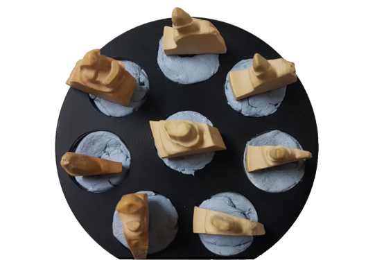
When working with more than 1 stamp, it is absolutely necessary that the adhesive putties supporting the stamps and the body of each stamp are separated by at least a few millimeters from each other. In this way, the scanning program can recognize each stamp,
Example of incorrect positioning:
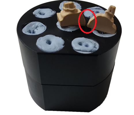
WARNING. The figure above shows the wrong location of the stamps. The putty support of each die should not connect, and the die bodies should not touch or be too close, because this incorrect arrangement does not allow the scanning software to identify and separate individual elements.
TIP The stamps should not be placed at an excessive angle, as the scanner cannot obtain the entire boundary line under these conditions. Therefore, you should always place the dies perpendicular to the surface of the turntable.
Impressions
The following images show the correct placement of the prints on the rotating table. This locking system, used in conjunction with the Smart Impression scanning function, is only available for MDS 500 models. The image below shows the impression correctly positioned on the rotating table. The impression must be attached to a special clip so that it is in the center of the rotating table. You can also use the wheel to adjust the angle.

There is no need to use other plates, the impression locking system must be located directly inside the scanner.
ADVICE
prints should be dry;
due to the impression material, it may be necessary to cloud it with special scanning aerosols;
it is recommended to cut out any unnecessary extra materials from the impression, which can cause the appearance of shadow areas;
make sure that the impression is placed so that it is in the center of the plate and has the correct slope;
3D scanning
Scan Options
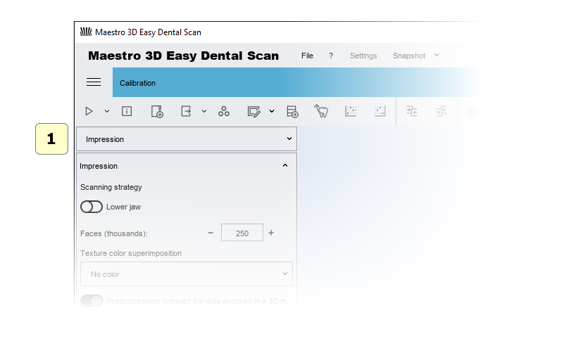
To start a new purchase, simply click New Purchase on the main toolbar.
In this window, you can select the type of object to be scanned and scan parameters.
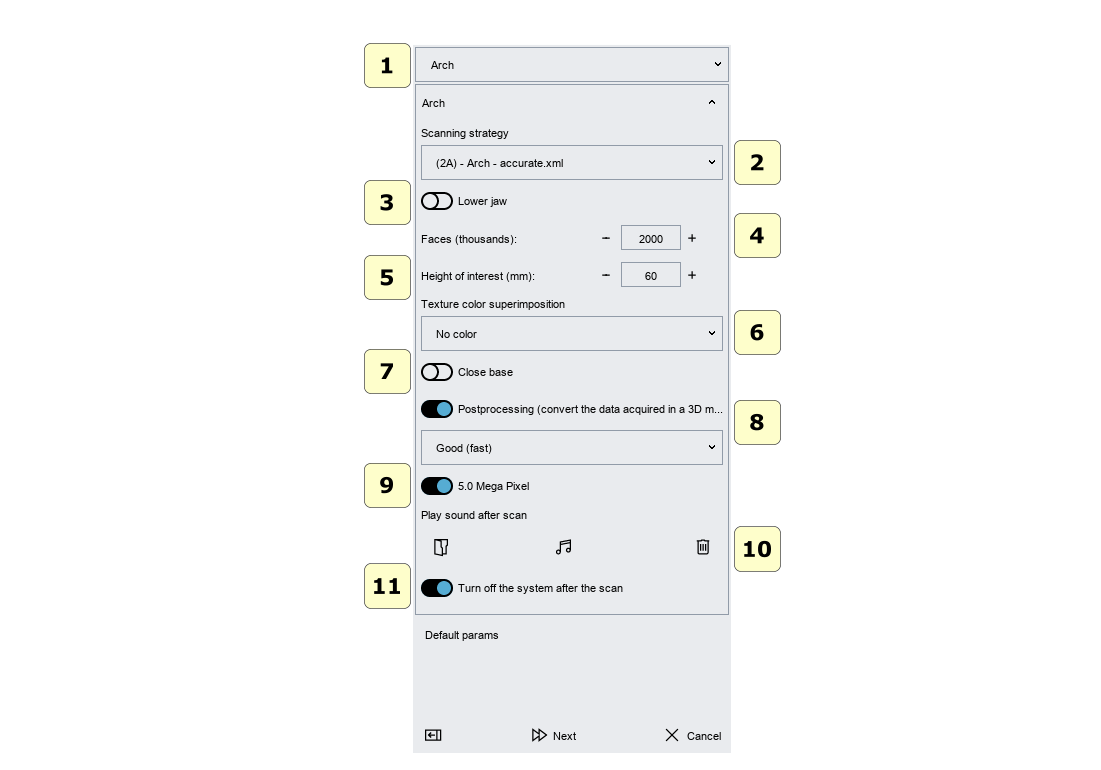
1 object type (arch, gum, wax back, stamps, impression, maxillofacial connection,…).
2 scanning Strategy: you can select a scanning strategy.
WARNING It may happen that with a small number of receipts (for example, 4-5), some models may not be able to perform a scan, because the overlap geometry between different images is insufficient. In this case, it is enough to increase the number of acquisitions in the strategy.
3 upper or lower model..
4 faces (triangles):
This number determines the number of triangles you want in your final model. The figure below shows the same model with 45000, 10000 and 2500 triangles. The precision and accuracy of the 3 models are equivalent. Among the 3 models, the number of triangles that approximate the surface geometry changes. The system always gets maximum accuracy and maximum accuracy. Only after obtaining the final three-dimensional model with the maximum number of triangles, it is destroyed to obtain the desired number of triangles. It is also possible to destroy the model later.
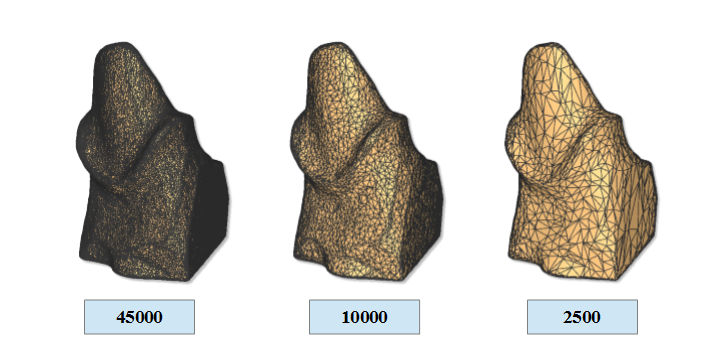
ATTENTION! The larger the number of triangles, the larger the STL file size.
30000 triangles-> 1.42 MB of STL file.
45000 triangles-> 2.14 MB of STL file.
250,000 triangles-> 11.90 MB of STL file.
5 Height of interest:
This parameter allows you to select the height of the model you are interested in (this height value is measured from top to bottom).
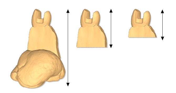
The first figure (from left to right) shows a stamp model in which the height of interest parameter is disabled, and then the Stamp is purchased completely, including the adhesive backing that supports it. Subsequent images show the same stump with the height of interest parameter set to 20 mm and 15 mm respectively (as you can see, the adhesive support of the putty is automatically removed).
It is important to remember that for the best use of this parameter, the model (arc, one or more dies, etc.) must be positioned perpendicular to the surface of the turntable.
IMPORTANT Cut out the model by selecting the height of interest, reduces the time of post-processing calculations and can improve the quality of results. (Especially the small volume of the stamp point cloud can lead to a better yield of the final model).
In any case, you can always delete an uninteresting geometry at any time by editing the model.
6 texture overlay color:
This requires an active texture mapping module. Activation is carried out through a software license. This is useful for getting models with an RGB color texture or a gray texture. For example, it helps to create very precise field lines, as noted on the model.
7 close the database:
If this option is set, the software will automatically close the lower base of the model.
8 post-processing (converting data obtained into a 3D model):
If this option is enabled, the system automatically postprocesses the received data and builds a surface of triangular geometry. If this option is not selected, the data will not be processed later. Post-processing of data received later is possible.
A good (fast): this option is recommended..
best (slow): this option requires more time for calculations and creates 3D models with more details.
TIPS To reduce the interaction time with the scanner when you have many models to scan, it is advisable not to perform post-processing after each scan. In this case, it is recommended to scan all models (do not check the “Post-processing” option, do not check the “Turn Off” option) and at the end of the work, turn off the system and select all elements (range maps) from the tree area and click the button for subsequent processing of all models.
9 Camera resolution, (only available with the MDS 500 scanner).).
10 play audio after scanning:
You can select the*. wav file to play after scanning and after post-processing.
11 Disabling after scanning:
Shutdown the system after the scan is finished.
TIPS Do not forget to turn off the system when not in use to avoid lamp burnout.
The Assembly of components
Assembly of the calibration kit
See the figure below for instructions on how to assemble the calibration kit after removing it from the packaging.
1 hex key;
2 plates;;
3 calibration plate;
Simply screw in the 4 supplied screws to connect the plate to the calibration plate. Be careful not to scratch or stain the calibration plate. It is recommended to handle the plate with gloves, so as not to stain it or leave fingerprints on it.
WARNING
store the calibration kit in a place protected from direct light and moisture;
do not clean with solvents or acids, and use only a dry cloth;
scratches or dirt on the calibration plate can compromise the calibration of the scanner;
handle cloth gloves carefully to avoid leaving fingerprints or dirt on the calibration plate.;
Assembling the impression holder
Follow the steps shown in the figure to properly assemble the impression plate after removing it from the package.
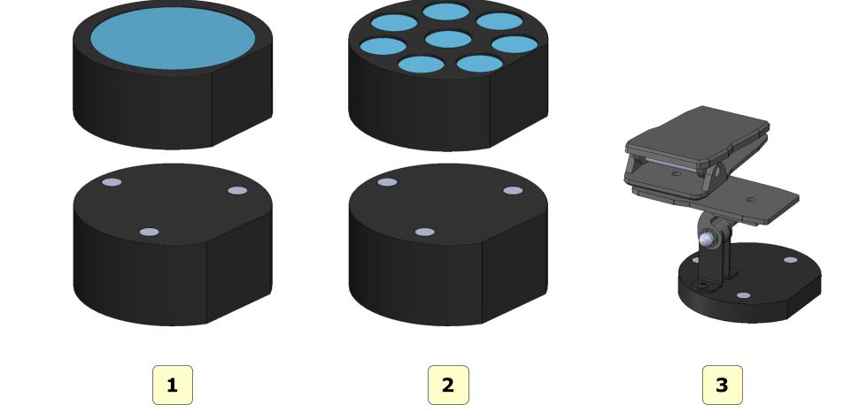
Tablets to scan
The figure below shows all the scanning plates that come with the MDS 500 scanner::
1 interface plate;
2 plate for arc model;
3 die plate;
4 impression plate;
UAC-User Account Control
To avoid difficulties and limitations in using the Software, you need to set the UAC-User Account Control slider to a minimum value, as shown in the figure below.
To enter the settings window: Control Panel-> User Account-> Change User Account settings. (Control panel-> User Account-> Change Settings User Account Control)
Administrator Rights
To run the Software, you must set the administrator rights correctly.
Follow the instructions as shown in the pictures below.
Right – click on the software icon to launch the context menu and select record properties.
Follow the steps as shown in the sequence from 1 to 4.
Click the Advanced button.
Select Run as Administrator.
Press the Ok button.
Press the Ok button.
User Interface
The figure below shows the structure of the user interface.
1) the Main toolbar.
2) The area of trees.
3) Information zone.
4) the bottom area.
5) Visualization \ Editing area.
The main toolbar
The main toolbar provides access to all the features of the Easy Dental Scan software.
1) New Scan-start a new scan or define a new scan strategy.
2) Scanner Status-activates a window that monitors the status of the hardware scanner.
3) New Group-adds a new group to the tree. You can move tree elements inside / outside the group by dragging the mouse.
4) Export-Export the selected element on the Z or Y axis. You can export to an open STL or PLY file.
5) Postprocess (conversion of scanned data into a 3D model) – the function is activated if the item is selected, and not subjected to subsequent processing. This operation may take several minutes to convert the scanned data from the scanner to a triangular geometry.
6) Editing a filter to Edit the selected elements. This is useful for removing artifacts due to scanning, for removing scanned putty, for performing hole filling, thinning, 2D \ 3D selection editing, etc
. Editing with a 2D rectangle
Editing with a 3D polyline
Editing with 2D selection
Filling voids
Pruning
7) Import a scanbody from library.
8) automatic stamp alignment procedure.
9) set the selected element as fixed or floating in the manual alignment procedure.
10) Comparison.
11) Measurements:
the point of measurement.
the angular measurements.
12) CAD-send selected elements to the design software.
13) Status of the projector.
Turn on.
Switch off.
The bottom toolbar
The bottom toolbar is an area of the screen that contains a progress bar that is displayed and updated each time the program is calculated, as well as controls for changing the visual settings of the visualization / editing area.
1) Touch screen mode (rotate / pan).
2) zoom in [PgDown key] / zoom in [PgUp key].
3) Reset the trackball [R key].
4) Parallel projection [O key], perspective projection [P key].
5) Smooth shading [S key], flat shading [F key].
6) photorealistic visualization.
7) shadow, (available if photorealistic rendering is enabled).
8) texture color, (real object color).
9) show / hide triangles, edges [E key], vertices [V key].
Visualization / editing area and information area
The visualization / editing area is the area of the window where models are rendered and all editing operations are performed.
In the visualization area, you can view models, edit and measure the distance between different points.
To view the models displayed in the visualization / editing area, the camera settings (position, zoom, and rotation) can be adjusted using a tool called trackball.
Trackball is very easy to use. Just use the left mouse button to rotate around the model, the mouse wheel to zoom in / out, and the right mouse button to move (pan) the camera.
The information area of the screen displays information related to the
Tree Area
The tree area contains all of the scanned models. Using groups allows you to maintain the order of scanned models. To select a model from the tree area, simply click on it with the left mouse button. The selected models will be displayed in the visualization area. To select more models, press and hold CTRL \ SHIFT.
Each of these elements corresponds to a set of operations available through the enabled icons on the main toolbar. This allows the user to access the main functions of the software.
Once you have access to the drop-down menu, as shown in the following figure, you can import an STL file into the tree.
Targets
Some examples of targets:
Relationship of the upper and lower jaw
Upper-Lower Jaw
Other examples of a dental arch
Impressions
Stamps
Correct location of objects
Arc or MMR
The following images show the correct position of the models on the turntable. The picture below shows the arch correctly positioned on the turntable. The arch should be placed in the center of the turntable, supported by putty or any other adhesive that keeps it well attached to the table.
The arch should be parallel to the surface and should not be tilted.
1 interface plate;
2 plate for the model;
3 objects to scan, arch or mandibular relations of the lower jaw (MMR);
Stamps
Up to 8 stamps can be placed on the scanner’s turntable at the same time.
1 interface plate;;
2 die plate;
3 stamps;
After the scanning process, the software automatically recognizes and separates individual stamps, adding an element in the tree area for each received stamp. The numbering (1..8) on the plate corresponds to the numbering of elements added to the tree area only if the plate is placed in front of the scanner.
An example of the correct positioning:
When working with more than 1 stamp, it is absolutely necessary that the adhesive putties supporting the stamps and the body of each stamp are separated by at least a few millimeters from each other. In this way, the scanning program can recognize each stamp,
Example of incorrect positioning:
WARNING. The figure above shows the wrong location of the stamps. The putty support of each die should not connect, and the die bodies should not touch or be too close, because this incorrect arrangement does not allow the scanning software to identify and separate individual elements.
TIP The stamps should not be placed at an excessive angle, as the scanner cannot obtain the entire boundary line under these conditions. Therefore, you should always place the dies perpendicular to the surface of the turntable.
Impressions
The following images show the correct placement of the prints on the rotating table. This locking system, used in conjunction with the Smart Impression scanning function, is only available for MDS 500 models. The image below shows the impression correctly positioned on the rotating table. The impression must be attached to a special clip so that it is in the center of the rotating table. You can also use the wheel to adjust the angle.
There is no need to use other plates, the impression locking system must be located directly inside the scanner.
ADVICE
prints should be dry;
due to the impression material, it may be necessary to cloud it with special scanning aerosols;
it is recommended to cut out any unnecessary extra materials from the impression, which can cause the appearance of shadow areas;
make sure that the impression is placed so that it is in the center of the plate and has the correct slope;
3D scanning
Scan Options
To start a new purchase, simply click New Purchase on the main toolbar.
In this window, you can select the type of object to be scanned and scan parameters.
1 object type (arch, gum, wax back, stamps, impression, maxillofacial connection,…).
2 scanning Strategy: you can select a scanning strategy.
WARNING It may happen that with a small number of receipts (for example, 4-5), some models may not be able to perform a scan, because the overlap geometry between different images is insufficient. In this case, it is enough to increase the number of acquisitions in the strategy.
3 upper or lower model..
4 faces (triangles):
This number determines the number of triangles you want in your final model. The figure below shows the same model with 45000, 10000 and 2500 triangles. The precision and accuracy of the 3 models are equivalent. Among the 3 models, the number of triangles that approximate the surface geometry changes. The system always gets maximum accuracy and maximum accuracy. Only after obtaining the final three-dimensional model with the maximum number of triangles, it is destroyed to obtain the desired number of triangles. It is also possible to destroy the model later.
ATTENTION! The larger the number of triangles, the larger the STL file size.
30000 triangles-> 1.42 MB of STL file.
45000 triangles-> 2.14 MB of STL file.
250,000 triangles-> 11.90 MB of STL file.
5 Height of interest:
This parameter allows you to select the height of the model you are interested in (this height value is measured from top to bottom).
The first figure (from left to right) shows a stamp model in which the height of interest parameter is disabled, and then the Stamp is purchased completely, including the adhesive backing that supports it. Subsequent images show the same stump with the height of interest parameter set to 20 mm and 15 mm respectively (as you can see, the adhesive support of the putty is automatically removed).
It is important to remember that for the best use of this parameter, the model (arc, one or more dies, etc.) must be positioned perpendicular to the surface of the turntable.
IMPORTANT Cut out the model by selecting the height of interest, reduces the time of post-processing calculations and can improve the quality of results. (Especially the small volume of the stamp point cloud can lead to a better yield of the final model).
In any case, you can always delete an uninteresting geometry at any time by editing the model.
6 texture overlay color:
This requires an active texture mapping module. Activation is carried out through a software license. This is useful for getting models with an RGB color texture or a gray texture. For example, it helps to create very precise field lines, as noted on the model.
7 close the database:
If this option is set, the software will automatically close the lower base of the model.
8 post-processing (converting data obtained into a 3D model):
If this option is enabled, the system automatically postprocesses the received data and builds a surface of triangular geometry. If this option is not selected, the data will not be processed later. Post-processing of data received later is possible.
A good (fast): this option is recommended..
best (slow): this option requires more time for calculations and creates 3D models with more details.
TIPS To reduce the interaction time with the scanner when you have many models to scan, it is advisable not to perform post-processing after each scan. In this case, it is recommended to scan all models (do not check the “Post-processing” option, do not check the “Turn Off” option) and at the end of the work, turn off the system and select all elements (range maps) from the tree area and click the button for subsequent processing of all models.
9 Camera resolution, (only available with the MDS 500 scanner).).
10 play audio after scanning:
You can select the*. wav file to play after scanning and after post-processing.
11 Disabling after scanning:
Shutdown the system after the scan is finished.
TIPS Do not forget to turn off the system when not in use to avoid lamp burnout.
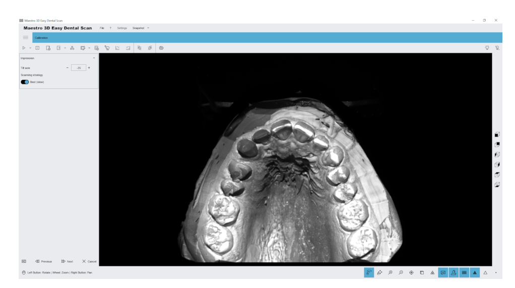
Scanning process
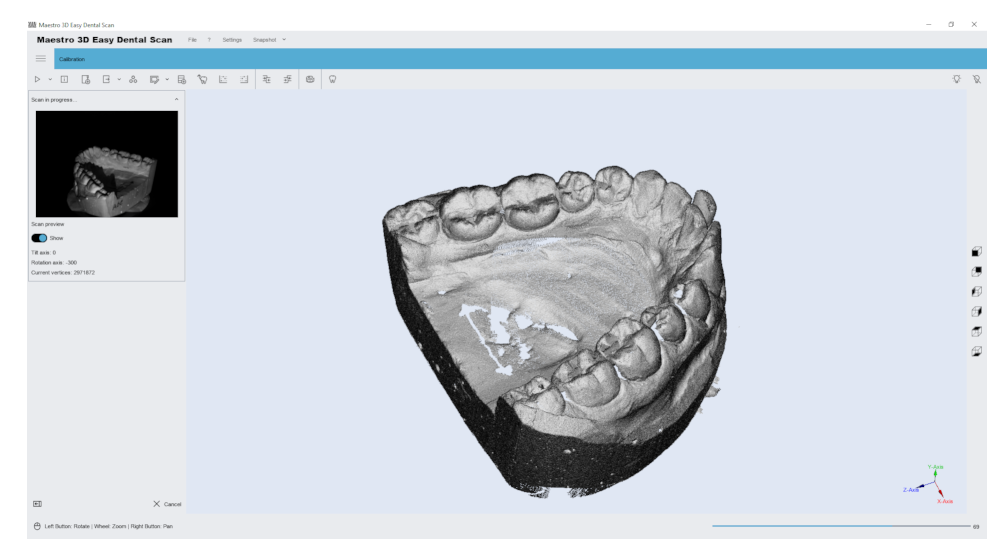
This window shows the progress of the scan phase. This may take a few seconds or a few minutes, depending on the chosen strategy. The window on the left shows getting a 2D image and a 3D image on the right.
After this operation, if the “Post-processing” option was selected, the program automatically generates the model surface from the obtained points and adds a new element to the tree area. Then, by selecting it in the tree area, the model is displayed in the visualization area.
If the “Post-processing” option was not checked, the program adds a new element with a gray icon to the tree area. Before you can perform any operation on this model, you must perform post-processing of the received data.
WARNING Before scanning, make sure that the model is correctly positioned on the turntable and that the front door of the scanner is closed. Do not move the scanner or its reference plane during scanning.
Scanning strategy
The following figure shows a window for managing scan strategies.
See below for details:
1) Scan group: MMR, Arch, Stamps, Impression.
2) the name of the strategy.
3) New strategy.
Save the current strategy.
Delete the current strategy.
4) Add tilt command (before adding, the command selects the degrees of rotation).
5) Add rotation command (before adding, the command selects the degrees of rotation).
6) Add a batch purchase. (before adding the command, select the number of steps of rotary table axis of rotation).
7) Commands:
Clear all commands.
Delete the selected command.
Add the tilt command to the starting position.
Add the rotate command to the original position.
Add an alignment group.
Add one purchase.
Run the strategy simulation.
RECOMMENDATIONS:
Each alignment group must contain more than one collection.
Each subsequent purchase must have an overlap area with the previous one.
Each alignment group must have an overlap area with the previous one. The software aligns each acquisition in each group, and then aligns the groups.
By default, each strategy starts and ends with the initial tilt position and the initial turn position.
The next step, as shown in the figure below, is the scanning phase. At this stage, it is important that the scanner door is closed so that ambient light does not interfere, reducing the contrast of structured light. It is equally important that the scanner is mounted on a stable table, and that it is not exposed to shock or vibration at this stage.

Once the print scan is complete, the software allows you to “clean” the scanned image before processing it. See also the #editing_with_2d_selection function. At this point, as shown in the figure below, you can remove all unnecessary parts of the scan.
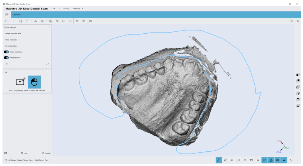
This way, the post-processing step that transforms the point cloud into a three-dimensional model will be faster and more efficient.
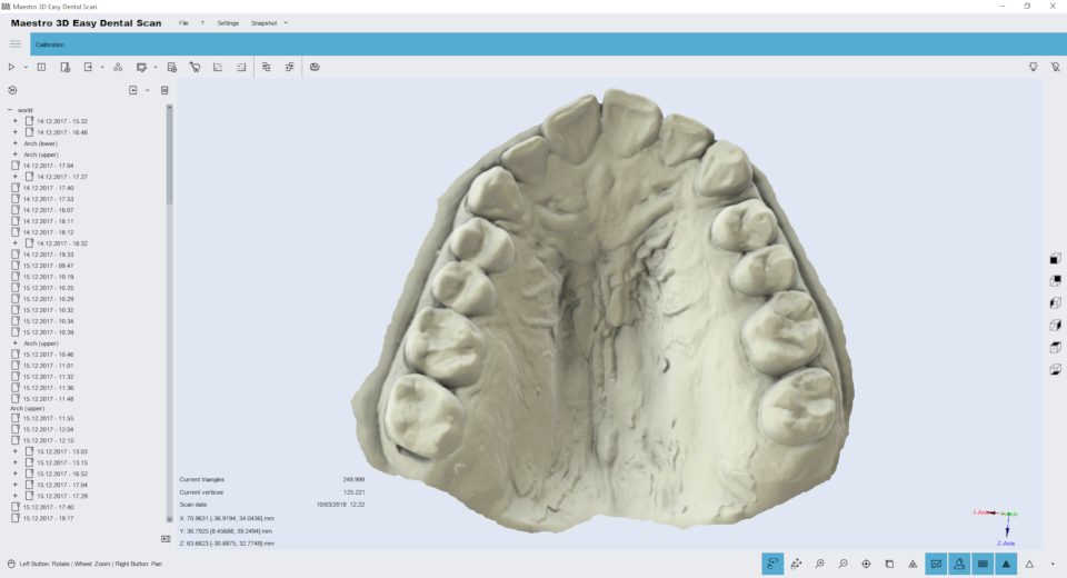
Below you can see the finished result of scanning impressions: photos of real impressions Registration of stamps
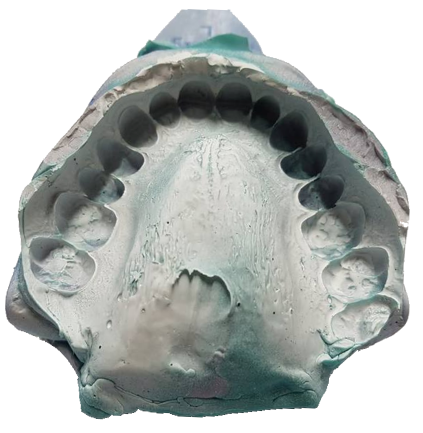
photo of the real impression
Registration of stamp
Stamp registration is fully automatic and allows you to replace low-resolution stamps obtained with an arch with high-resolution stamps obtained without an arch.
In the tree area, select the arch with the stamps (which should be replaced).
After that, the arch is displayed in the visualization area with a limited view, so that it can only be viewed from above. In detail:
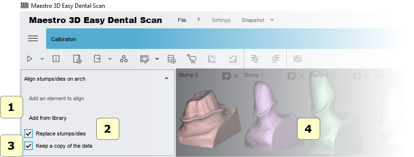
1) to add stamps \ scanning body to replace, select them in the tree area and click the buttons.
2) If the stamp replacement check box is selected, the high resolutions of one stamp will be replaced by a lower resolution stump scanned in an arc. This is recommended if you need to work with dental card software. If you do not select this option, the Stamp will only be aligned.
3 if this option is enabled, the software creates a backup copy of the data.
4) the preview pane of stamps.
ADVICE: If the selected stamp is not correct, simply close the preview window to remove it from the registration process. You can register up to 16 stamps at a time.
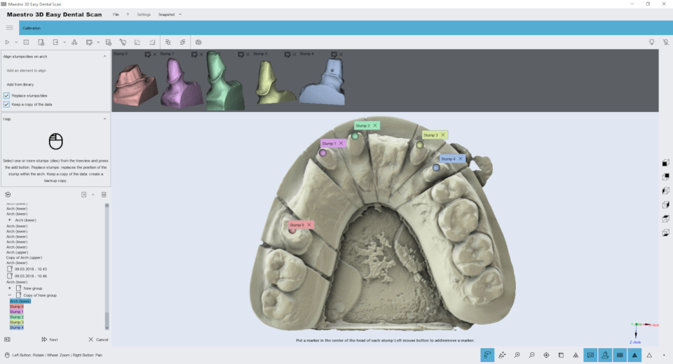
After selecting and adding stamps, double-click the center of the low-resolution stamp head to indicate the position where each Stamp should be registered.
Double-click on the stamp head to add a sphere (called a marker) associated with the number to the visualization area. The color and number, as shown in the picture, are associated with the correct stump.
ADVICE: To delete a marker, double-click it.
Before proceeding with registration, make sure that each token is associated with the correct stump. To continue registration, click “Next”.
The progress bar located on the bottom toolbar will display the progress of the registration process.
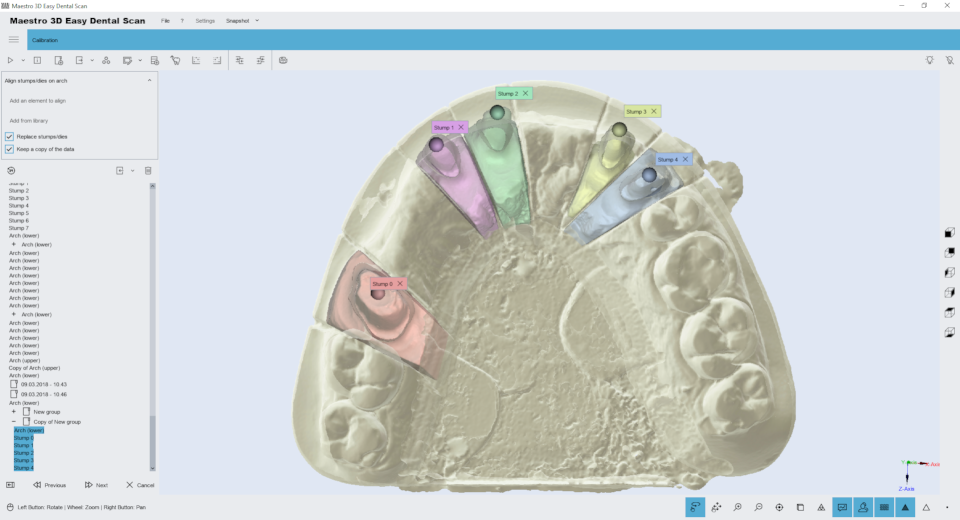
At the end of the registration process, the registration result is displayed in the visualization area, where low-resolution stamps have been replaced by high-resolution stamps. If you are satisfied with the result, click Next to complete and save the registration you received, or click the previous button to return to the previous step.
If one or more stamps are not aligned correctly, click the close button next to the marker, and then, after completing this task, you will be able to re-register only these stamps.
If the registration is not satisfactory, please make sure that the markers have been placed in the correct position as explained earlier (in the center of the head of each stamp and in the correct order).
ADVICE: It is also possible to replace the stamps on the arch with manual alignment.
Manual alignment 3-2-1
Using the manual registration process, you can align any pair of models. For example, it is useful to align the Stamp on the arch or arch or bite with the reference model of the antagonists.
To align the two models, you must select a fixed model (for example, maxillary mandibular connection) and a floating model (example of an arc). The following image shows the manual setup window.
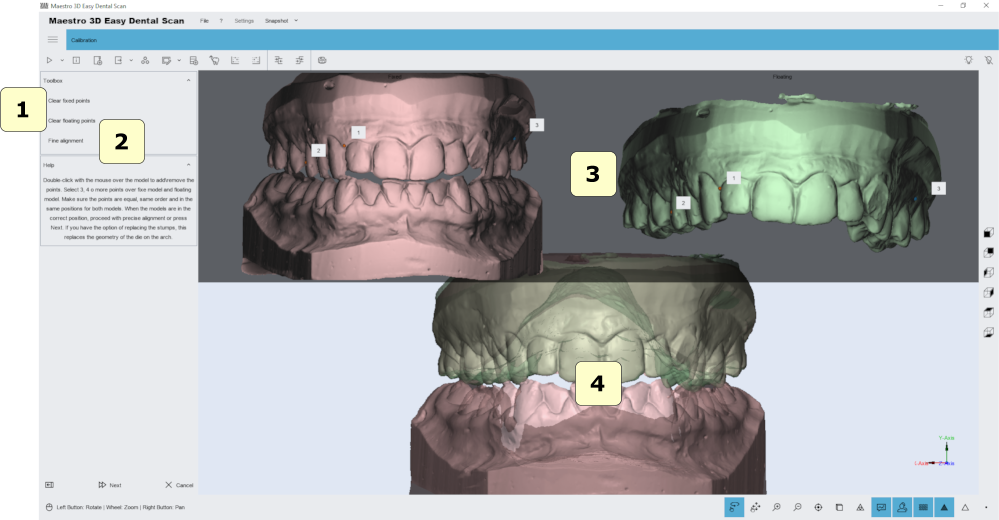
To align a floating object to a fixed object, you must add multiple points in the fixed model (which is displayed to the left of the screen), and the same points must be added to the floating object (which is displayed to the right of the window). You must add at least 3 points to each model.
1) clear fixed or floating point.
2) precise alignment. Improves the initial alignment set by the points entered by the user.
4) the preview area, which shows the fixed and variable model.
5) the resulting alignment.
TIP: Double-click with the left mouse button to add a point above the model.
The edit filters
Editing with a 2D rectangle
Features of editing a rectangular selection. The image below shows the filter window.
By holding down the SHIFT key and the left mouse button, you can draw a rectangular selection area. The area of the selected geometry will be colored red. The toolbar on the left side of the screen has buttons to delete the selected area, invert the selection, clear the selection. To save your changes and return to the previous screen, click Next .
Editing with a 3D polyline
Features of editing the selection of a 3D polyline. The image below shows the filter window.
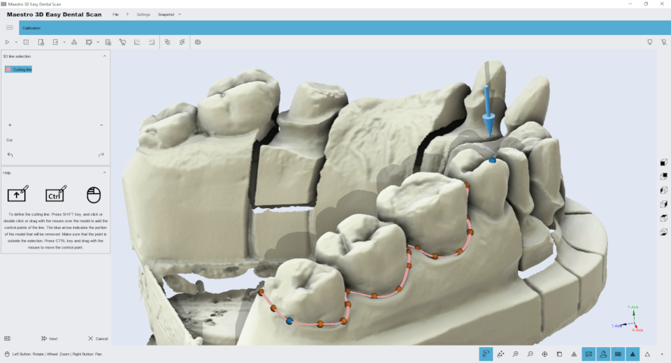
Hold down the SHIFT key and the left mouse button to draw a 3D polyline over the model. This function is useful for removing gum or wax from the model. Once you’ve drawn the polyline, just double-click on the area you want to delete. The image below shows the filtering result.
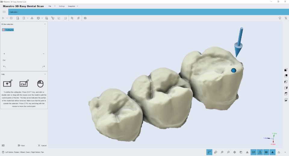
To save your changes and return to the previous screen, click Next .
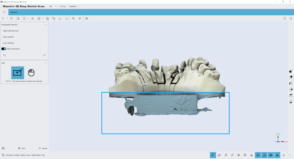
Editing with 2D selection
The editing capabilities of the 2D array. The image below shows the filter window.
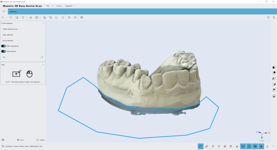
By holding down the SHIFT key and the left mouse button, you can draw a 2D selection area. The area of the selected geometry will be colored blue. At the top of the screen are buttons to delete the selected area, invert the selection, clear the selection. To save your changes and return to the previous screen, click Next .
Filling of cavities
Edit the details of filling in the holes. The image below shows the filter window.
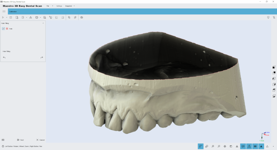
Just click the Fill Holes button on the toolbar on the left side of the screen to fill all the holes in the model. This is useful for filling the lower part of the model base. The image below shows the filtering result.
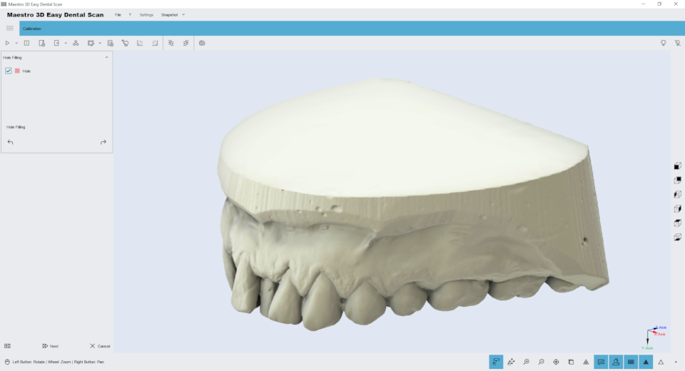
To save your changes and return to the previous screen, click Next .
Compression
Editing feature of thinning. You can use this function to reduce the number of triangles in the model. The filter removes more triangles in areas of the model with fewer elements, preserving the best details in the most important areas of the model, such as the field line or tooth geometry. The image below shows an initial model of 700,000 triangles:
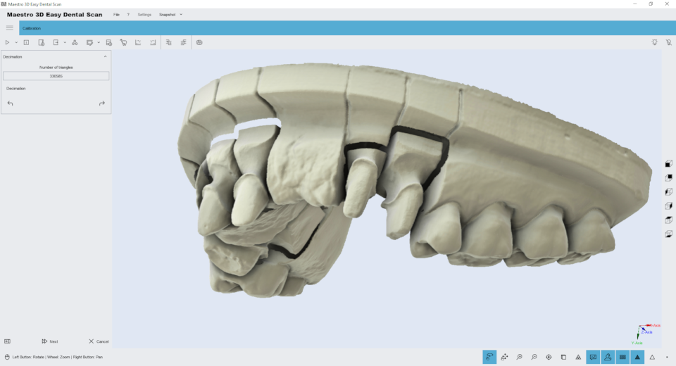
Simply select the triangle number and click the Decimation button on the toolbar on the left side of the screen to reduce the number of model triangles. To save your changes and return to the previous screen, click Next .
The figure below shows the same model with a quarter resolution, 160,000 triangles. As you can see, the details are not lost, and the margins of the fields are still clearly visible and detailed.

we can see that even at low resolutions, as shown in the figure below, around 80,000 triangles, the quality of the 3D model is still noticeable.

3D Comparison
To compare models, you can choose a “reference” model and a “test” model. The following image shows a three-dimensional comparison performed on two different scans of the same model. As you can see from the color map, the two models are almost identical.

ADVICE:before comparing two models, it is necessary that they are aligned with each other, for example, using the #Manual_3-2-1_alignment function.
Measurements
To perform measurements of length or angles, select the item to check, and then go to the Measurement function.

TIPS: Double-click the left mouse button to add a point.
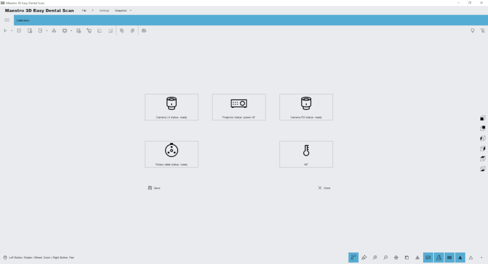
Scanner Status
With this function, you can monitor the status of the scanner equipment. The window will show the status of each hardware device inside the scanner.
Dental Studio – Ortho Studio module Wizard
This scanning wizard helps the user to make all necessary scans and alignments to obtain a complete case to work into Dental Studio software – Ortho Studio module.
The following image shows the first step of the scan. In this phase you can scan maxillary and mandibular relationship. In this window you can change the scanning settings and the scanning strategy.


The following image shows the result of the maxillary and mandibular relationship. Now the user can scan the lower arch.

The following image shows the result of the lower arch. Now the user can scan the upper arch.

The following image shows the result of the upper arch. Now it’s possible to perform the alignment of the upper and lower arch respect to the relationship. The procedure of alignment is the Manual 3 2 1 Alignment.

After that the scanning software send the correct data to the Ortho Studio software.

Master of dental restoration
This scan wizard helps the user perform all the necessary scans and alignments to get a complete case for working with all the dental cameras integrated into the Maestro 3D scanner. All Maestro 3D scanners are fully integrated with leading design programs such as exocad and maestro_3d_dental_studio_-_user_manual#Dental_restoration_.2F_Dental_CAD. The following figure shows an example of the scan wizard step. In this window, you can change the scan settings and scan strategy.
Exocad Wizard
To integrate the scanner with the autocad software, you need to edit the file \exocad-folder-installation\DentalDB\config\defaultsettings-db.xml as shown in the figure below.
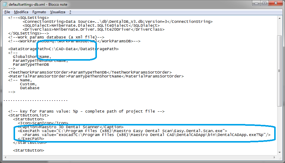
<<Data Storage Path>C:\CAD-Data</Data Storage Path>
…
<<Start Buttons>
<Button>
<<Icon>Cran Icon</Icon>
< caption > Maestro 3D Dental Scanner < /caption >
<<Exec Path value=”C:\Program Files\Maestro Easy Dental Scan\Easy.Dental.Scan.exe”>
<Params value=”exocad?C:\Program Files\exoCAD\DentalCADApp\bin\DentalCADApp.exe?%p”/>
</</Exec Path>
</Button>
…
< < Exec Path value = this is the path where you installed Easy Dental Scan.
<Params value =is this an exocad string? and the path you installed dentalcadapp with ?%p at the end of the line.
Calibration
MDS500 Calibration
Maestro_3D_Dental_Scanner_-_Calibration
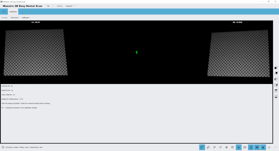
Click the Calibration tab, place the calibration sample in the scanner, and then click Connect. Once the images of the two cameras appear as shown above, click the Calibrate button .
The calibration process is fully automatic, during which the optics, motors and corresponding axes are calibrated. Wait until an error or error message appears on the screen. After that, you can delete the calibration sample, save it, and continue scanning.
The calibration process takes several minutes. During the calibration process, it is recommended to keep the door closed and not touch the table where the scanner is located.