
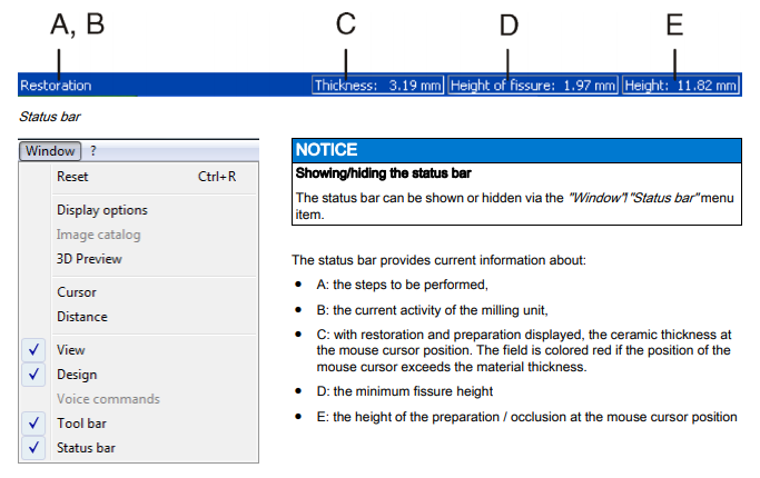
CEREC Biogeneric
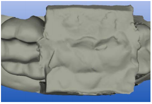
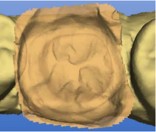
CEREC Biogeneric is the first method which is able to reconstruct lifelike occlusal surfaces. On the basis of the features of a patient’s single intact tooth, the program extrapolates the naturally created morphology of other teeth. The biogeneric occlusal design functions for all single tooth restorations and fully anatomic bridges.
Currently, all occlusal design approaches are based on dental libraries and
databases containing data records of various standard teeth. Conventional
CAD/CAM programs retrieve a matching tooth from the archive, and then generate a design proposal for the given clinical situation. The user then manually edits and adapts this proposal. The biogeneric occlusal design is to replace the “dental database” design procedure applied in previous CEREC software versions. It will now be possible to create crowns, inlays, onlays, veneers, and anatomically sized bridges in a fully automated manner. The reconstruction can be based on any intact patient tooth from the same type, i.e. posterior tooth or anterior tooth. The often time-consuming process of manually adjusting the tooth to the clinical situation is now virtually a thing of the past. Moreover, due to the standardized and largely automated routines, the new software is easy to get to grips with and use.
Tool bar of the CEREC 3D software
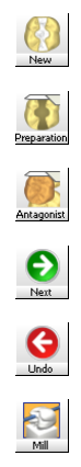 Description of the icons Explanation on the CEREC 3D mode tool bar
You can show or hide the tool bar via the “Window” / “Tool bar” menu item. Inactive functions appear dimmed.
● Create a new restoration
● Scan/acquire prepared tooth (preparation)
● Scan/acquire antagonist/registration
● One design step forward (Next)
● One design step backward (Undo)
● Starting the milling process
You can drag the tool bar with the mouse and drop it anywhere on the screen. It can be docked at the left, right, top or bottom edge of the screen, as is usual with Windows programs. Via “Window” / “Reset” (“Ctrl+R”) it can be restored to the position it had on delivery (left edge of screen).
Menu bar of the CEREC 3D software
The menu bar at the top of the window allows you to select further program functions which cannot be accessed via the tool bars.
![]()
The following menus are available in the CEREC 3D mode:
● “Restoration”
● “Settings”
● “Window”
● “?”
 Restoration menu in the CEREC 3D mode
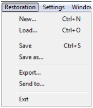 Restoration menu in the CEREC 3D mode
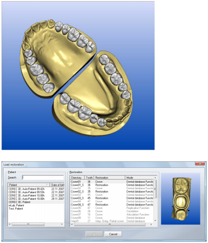 Loading a restoration in the CEREC 3D mode
In the dialog box “Load restoration” all restorations are displayed in the CEREC 3D mode. However, optical impressions taken in the Master mode aredimmed and can not be loaded.
A detailed description of the individual menu items can be found under “Restoration menu”.
Settings menu in the CEREC 3D mode
With the “Settings” menu, you can adapt and change the following menu
items: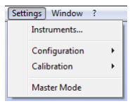
● “Instruments”
● “Configuration”
● “Calibration”
● “Master Mode
Instruments
This menu item allows you to change worn/defective milling instruments. Also refer to the chapter “Changing burrs” in the Operating Instructions of the milling unit.
Configuration
Under this menu item, you can check and modify the factory-set configurations.
● “Devices…”
● “Options”
All connected milling units can be displayed and configured under the menu item “Settings”/”Configuration”/”Devices…”
Via the menu item “Settings”/”Configuration”/”Options” you can set the following:
● Show/hide docking bar
● “Automatic capture” (with CEREC Bluecam only)
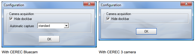
The docking bar is hidden in the 3D preview. If you move the mouse pointer to the lower part of the respective image field, the docking bar dynamically appears.
If you place a check mark in front of “Hide dockbar” , the docking bar will be displayed permanently.
For impressions acquired with the CEREC Bluecam, you can use the “Automatic capture” option to set the sensitivity to shaking of the automatic acquisition technique. The setting options are available:
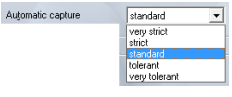 ● “very strict”
● “strict”
● “standard”
● “tolerant”
● “very tolerant”
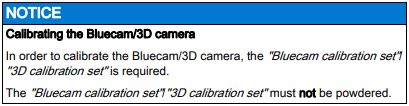
Calibration
Via the “Calibration” menu item you can…
● calibrate the “3D camera”,
(see the chapter “Calibrating the Bluecam/3D camera” in the Operating
Instructions for the acquisition unit).
 ● calibrate the “Milling unit”,
(see chapter on “Calibrating the milling unit” in the operating instructions for the milling unit).
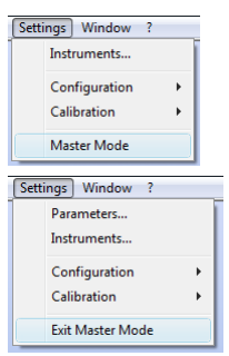 Master Mode
If you select “Settings”/”Master Mode” from the menu, all software functions are shown.
If you select the “Settings” / “Exit Master Mode” menu item, the unit is reset to its delivery status (CEREC 3D Mode).
A detailed description of the individual menu items can be found under “Settings menu”.
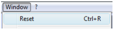
Window menu in the CEREC 3D mode
You can restore the default setting for the display of the windows/tool bar on the screen:
“Window” / “Reset” or “Ctrl+R”
“?” menu in the CEREC 3D mode
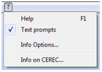 If the menu item “Text prompts” the next work step is described in a balloon in the status bar.
A detailed description of the individual menu items can be found under “”?” menu”.
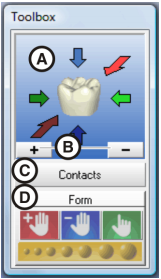
Toolbox window
Introduction
 You can drag the window with the mouse by grabbing its title bar and drop it at any position on the screen. Via “Window” / “Reset” (“Ctrl+R”) it can be restored to the position it had on delivery (right edge of screen).
● A: Standard views
For a detailed description, see “Standard views”
● B: Zoom tool
For a detailed description, see “Zoom tool”
● C: Showing/hiding contact surfaces (“Contacts”)
For a detailed description, see “Showing/hiding contact surfaces”
● D: Form tool (“Form”)
For a detailed description, see “Form tool”
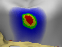
Showing/hiding contact surfaces
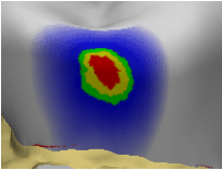 By clicking the button marked “Contacts” you can show/hide the contact surfaces to the neighboring teeth and to the antagonist. The neighboring teeth are then hidden or shown. When the contact surfaces are shown, a color scheme with the following meaning appears:
● blue: Clearance 0-1 mm
Smaller surface – larger clearance
● green: Penetration 0-50 µm
● yellow: Penetration 50-100 µm
● red: Penetration >100µm
With the “Form” tool, you can design the contact surfaces according to your wishes.
Note: 3D Preview
In the 3D mode, the 3D Preview displays only the “Preparation” and “antagonist” image fields. There is no image field for occlusal impressions.
User interface in Master Mode
Description of the user interface
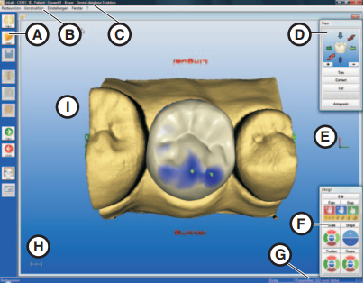
Main menu
CEREC 3D features a menu-controlled user interface enabling you to scan
preparations and then design and mill the required restorations.
Screen displays guide you through the design process and give you a continuous overview of which program step is currently being performed.
The main menu consists of:
● A: Tool bar
● B: Menu bar
● C: Program window title,
● D: View window
● E: Coordinate system
● F: Design window
● G: Status bar
● H: Scale (1 mm)
● I: Design window (3D viewer)
You can show or hide the following windows/bars:
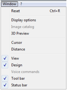 ● “View”
● “Design”
● “Tool bar”
● “Status bar”
Tool bar
Explanation on tool bar
You can show or hide the tool bar via the “Window” / “Tool bar” menu item. Unavailable functions are grayed out (e.g. Occlusion in the example below).
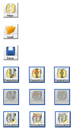 ● Create a new restoration
● Load restoration
● Save restoration
● Scan/acquire prepared tooth (preparation)
● Scan/acquire unprepared tooth (occlusion)
● Scan/acquire dynamic occlusion impression (articulation)
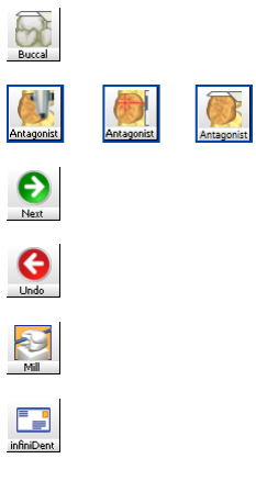
● Acquire a buccal optical impression
● Scan/acquire antagonist/registration
● One design step forward (Next)
● One design step backward (Undo)
● Starting the milling process
● Send restoration to infiniDent
 You can drag the tool bar with the mouse and drop it anywhere on the screen. It can be docked at the left, right, top or bottom edge of the screen, as is usual with Windows programs. Via “Window” / “Reset” (“Ctrl+R”) it can be restored to the position it had on delivery (left edge of screen).
View window
Introduction
You can display or hide this window via the menu item “Window”/”View” .
Inactive windows appear dimmed. You can drag the window with the mouse by grabbing its title bar and drop it at any position on the screen. Via “Window” / “Reset” (“Ctrl+R”) it can be restored to the position it had on delivery (right edge of screen).
View window
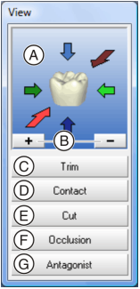 ● A: Standard views
● B: Zoom tool
● C: Showing/hiding the neighboring teeth (Trim)
● D: Showing/hiding the contact to the neighboring tooth (Contact)
● E: Cut tool
● F: Showing/hiding the occlusion/articulation/gingival mask
● G: Show/hide antagonist
Standard views
The objects in the Design window can be displayed in six predefined views by clicking the corresponding arrows:
● “Mesial”
● “Distal”
● “Buccal” / “Labial”
● “Lingual”
● “Cervical”
● “Occlusal” / “Incisal”
When you point to one of these arrows with the mouse cursor, the direction of the view is indicated.
When you click the arrow, the object is turned into this view.
There are two ways to display the “Mesial”, “Distal”, “Buccal” / “Labial” and “Lingual” views:
If you have changed the display of the objects with the zoom tool, you can reset this change by clicking on the tooth in the View window.
Zoom tool
The objects displayed in the Design window can be zoomed in and out as follows:
● step by step, by repeatedly clicking the “+” sign (zoom in) or the “-” sign (zoom out)
● continuously, by pressing and holding down the “+” sign (zoom in) or the “-” sign (zoom out)
● by pressing the center mouse button and moving the mouse:
– forward, you zoom the 3D view in
– back, you zoom the 3D view out
● by simultaneously pressing the left mouse button and the Shift key and moving the mouse:
– forward, you zoom the 3D view in
– back, you zoom the 3D view out
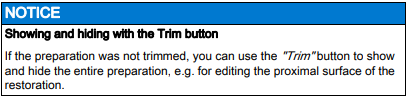
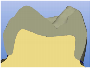
Showing/hiding the neighboring teeth
You can hide the neighboring teeth by clicking the “Trim” button.
For the case that parts of the neighboring teeth are disturbing during input of the preparation margin, trimming off the disturbing parts is possible. For this purpose, you can hide parts of the image after image acquisition (see “Trimming the preparation [ ➙ 105]“). You can redisplay the neighboring teeth by clicking the “Trim” button again.
 Showing/hiding the contact to the neighboring tooth (Contact)
You can show or hide the contact surface to the neighboring tooth by clicking the “Contact” button.
You can click on the “Contact” button to open the “Contact Options” dialog box.1 .
You can have the appropriate proximal contact defined automatically by clikking the corresponding button
 If you click the “Contact” button, a color scheme with the following meaning appears on the contact surfaces:
 ● blue: Clearance 0-1 mm
Smaller surface – larger clearance
● green: Penetration 0-50 µm
● yellow: Penetration 50-100 µm
● red: Penetration >100µm
You can use the design tools “Scale”, “Shape”, “Form”, and “Drop” to design the contact surfaces according to your wishes.
Cut tool
To open the “Cut” window, choose “Cut” or “Ctrl+C”.
You can place a cut plane through the restoration and preparation by clicking the “Cut” tool. The cut plane lies parallel to the screen plane. The cut plane can be moved parallel in two ways:
● step by step, by repeatedly clicking the “+” or “-” Cut semicircles
● continuously, by keeping a semicircle pressed.
CEREC For bridges, the cut surface is displayed in the status bar.
 Cut plane
To exit the “Cut” tool, click the highlighted “Cut” bar.
Close the “Cut” window by clicking x (Close) or the “Cut” button
Showing/hiding the occlusion/articulation
Occlusion
If an image field of the occlusion exists, you can show or hide it with the help of this button.
Articulation
This function can be used only for the following:
● “Restoration”: “Crown”
● “Design technique”: “Articulation”
If a dynamic occlusion impression (FGP, Functionally Generated Path) exists, it can be shown or hidden with the help of this button.
If you click the “Articulation” button, the 3D model of the dynamic occlusion impression is displayed and an additional dialog box is opened with the “Fit Restoration” button.
 Interfering_contact_FGP
If you click the “Fit Restoration” button, all of the interfering contacts of the restoration which “protrude out of” the FGP will be virtually milled so that they disappear.
 Interfering contacts milled
Show/hide antagonist
By clicking the button marked “Antagonist” you can show/hide the Antagonist window.
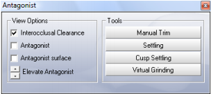
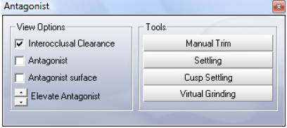 Antagonist window
In this window, under “View Options” you can activate or deactivate the following:
● “Interocclusal Clearance”
● “Antagonist”
● “Antagonist surface”
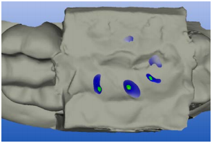
Interocclusal clearance
Description When “Interocclusal Clearance” is activated, a color scheme with the following meaning of the colors appears on the restoration:
Explanation of colors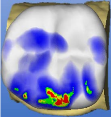 ● blue: Clearance 0-1 mm
Smaller surface – larger clearance
● green: Penetration 0-50 µm
● yellow: Penetration 50-100 µm
● red: Penetration >100µm
Design tools
You may use the “Scale”, “Shape”, “Form” or “Drop” design tools to adapt the distance.
Antagonist
If “Antagonist” is activated, the optical impression of the centric bite registration appears above the restoration.
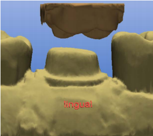 Antagonist displayed
By clicking the buttons next to “Elevate Antagonist” you can elevate or lower the registration. You obtain a better view onto the occlusal surface by elevating the antagonist. You can view the restoration from all directions and adapt it with the “Design”tools.
Antagonist surface
If “Antagonist surface” is activated, the occlusal surface of the antagonist/registration appears above the restoration.
Antagonist surface displayed
By clicking the buttons next to “Elevate Antagonist” you can elevate or lower the registration. You obtain a better view onto the occlusal surface by elevating the antagonist. You can view the restoration from all directions and adapt it with the “Design”tools.
Tools subgroup
 Antagonist window
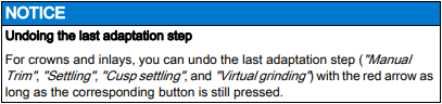
With the “Manual Trim” button in the “Antagonist” dialog box you can also hide image regions at a later point in time. For posterior tooth crowns with antagonist (design technique “Biogeneric” or “Biogeneric reference”), the “Settling”, “Cusp settling” and “Virtual grinding” buttons all have the same function as in the automatic crown suggestion (see “Options” in the “Settings” Chapter). You can use these functions if you have changed the suggested crown with the “Design” tools and would like to redefine the occlusal contacts.
For inlays/onlays in the design technique “Biogeneric” with antagonist, you can automatically set the occlusal contacts with these buttons. Automatic adaptations to the antagonist are performed for the inlay/only initial suggestion.
Settling button
With this button, the restoration is adapted to the antagonist so that the resulting contact situation is as stable as possible. The contacts should have as little penetration volume as possible. The morphology of the occlusal surface is not changed.
Cusp settling button
If the restoration features a cusp tip, the “Cusp settling” button is automatically enabled. This button triggers automatic adaptation of the individual cusps of the restoration to the antagonist. The cusps are adapted to the antagonist so that the resulting contact situation is as stable as possible. The morphology of the occlusal surface is changed.
Virtual grinding button
This button can be used to virtually grind the existing occlusal contacts. This function removes the red contacts down to a size that you have defined in the parameter dialog under “Occlusal contact strength”.
When designing inlays/onlays and crowns which are not automatically adapted, we recommend that you initially adapt the restoration to the present situation with the “Design” tools. Then you can finalize the contact situation with the following buttons in this order:
1. “Settling”
2. “Cusp settling”
3. “Virtual grinding”
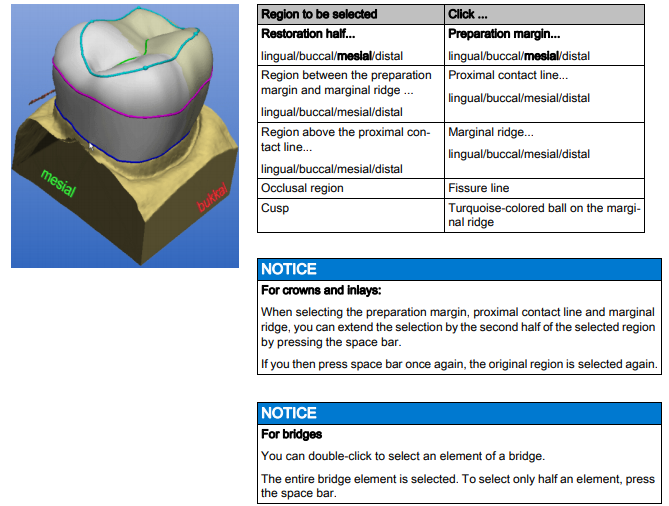
 Design window
You can display or hide this window via the menu item “Window” / “Design” . Unavailable functions appear dimmed, e.g. “Position”.
You can drag the window with the mouse by grabbing its title bar and drop it at any position on the screen.
When you select “Window” / “Reset” , the window returns to its default position (right screen margin).
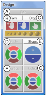 The following “Design” tools are described in this section:
● A: Editing tool (Edit)
● B: Form tool
● C: Wax drop (Drop)
● D: Scaling tool (Scale)
● E: Shaping tool (Shape)
● F: Positioning tool (Position)
● G: Rotation tool (Rotate)
Editing tool (Edit)
Click the “Edit”to activate/deactivate the Editing function.
 Editing function
The editing function can be applied to all the design lines. The design lines
are displayed automatically and have different color coding.
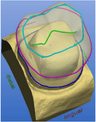
Colors of design lines
Design line Color
Preparation margin, base line, gingival line
blue
Proximal contact line pink
Marginal ridge, labiolingual line turquoise
Fissure, cutting edge or copying line Green
Editing is effective only in the viewing plane.
Editing a construction line
1. Click the “Edit” button.
2. Double-click a construction line to set the first point of the correction line.
3. Click to set further points of the correction line.
4. Setting the end point of the correction line:
Closed line (e.g. crown equator)
Double-click the construction line
Open line (e.g. fissure line)
Double click at the desired new end point of the line.
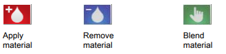
Form tool (Form)
By clicking the “Form” button, you can activate or deactivate the “Form” tool.
 You can use this function to
● apply material
● remove material
● blend material
Clicking on the symbol activates the corresponding mode.
Changing the size of the layer to be applied
When you start this tool, the diameter of the layer to be applied is 1.35mm.
Slider
The slider allows you to modify the size of the layer to be applied.
The next layers will be applied using this size. This size remains active until you change the size again or deactivate the Form tool.
The ratio between material thickness and radius of the applied layer is 1:70
Wax drop (Drop)
By clicking the “Drop” button, you can activate or deactivate the wax drop
function.
 You can use this function to
● apply material
● remove material
● blend material
Clicking on the symbol activates the corresponding mode.
Modifying the wax drop size
When you start this tool, the diameter of the drops is 1.08mm.
Slider
The slider allows you to modify the size of the drops.
The next drops can be applied using this size. This size remains active until you change the size again or deactivate the “Form” tool.
The ratio between material thickness and radius of the drops is 1:70
Applying material
Application can be performed in two ways:
● Drop by drop, by clicking the desired point of the restoration
● Apply a row of drops in material color by holding down the left mouse button and moving the cursor. The density of the drops is controlled by the speed with which you move the cursor.
Removing material
Removal can be performed in two ways:
● Drop by drop, by clicking the desired point of the restoration
● Remove a row of orange colored drops by holding down the left mouse
button and moving the cursor. The density of the drops is controlled by
the speed with which you move the cursor.
Blending material
The cursor assumes the shape of a hand and can then be used to blend or
smoothen the surface locally; to do so, press and hold down the left mouse
button.
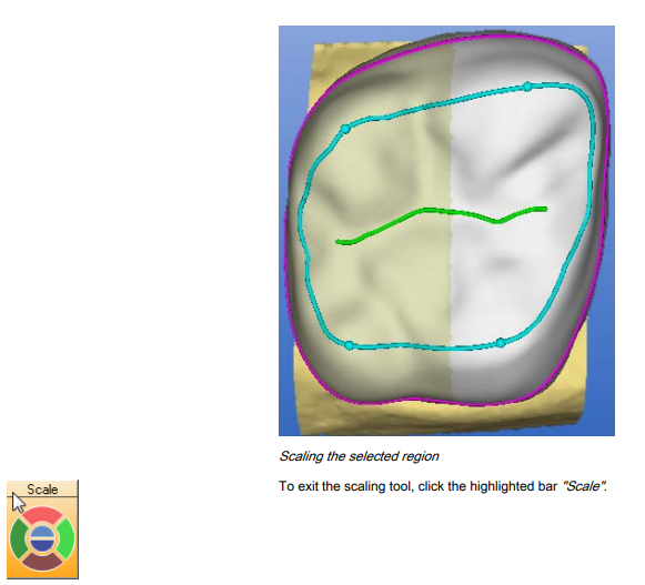
Scaling tool (Scale)
By clicking the “Scale” tool, you can activate the scaling function. This function enables you to scale a selected region. Scaling range
First select the region to be scaled by clicking one of the lines.
Selecting the scaling region
Once you have selected a region, you can modify it as follows:
● step by step, by repeatedly clicking a segment of the circle (e.g. buccal)
● continuously, by keeping a segment of the circle (e.g. buccal) pressed.
 Shaping tool (Shape)
You can smoothen surfaces and apply or remove material with the “Shape” tool:
● along an open line or
● inside a closed area
To exit the “Shape” tool, click the highlighted button marked “Shape” .
Applying material along an open line
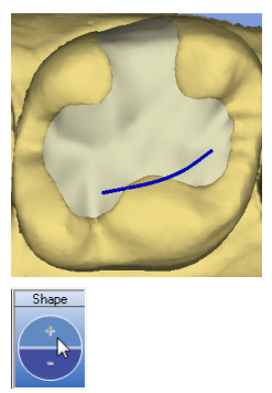 1. Start to draw a line by double-clicking the restoration.
2. Draw the line along which you want to apply or remove material by clikking.
3. Set the line end by double-clicking.
4. You can raise (+) or lower (-) the line:
step by step, by repeatedly clicking the “+” or “-” “Shape” semicircle or
continuously, by keeping the “+” or “-” semicircle pressed.
Applying material inside a closed area
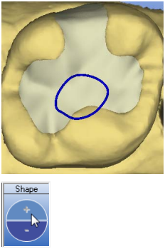 1. Start to draw a line by double-clicking the restoration.
2. Draw the area inside which you want to apply or remove material by clikking.
3. Set the line end by double-clicking the starting point.
4. The region inside the area is activated, you can apply (+) or remove (-)
material:
step by step by clicking the “+” or “-” “Shape” semicircle or
continuously, by keeping the “+” or “-” semicircle pressed.
Smoothing an area
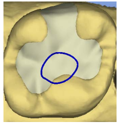 You can also smoothen a previously defined area with the “Shape” tool.
1. Start to draw a line by double-clicking the restoration.
2. Draw the area inside which you want to smoothen the surface by clicking.
3. Set the line end by double-clicking the starting point.
4. Activate the smoothing function by pressing the spacebar.
ª The surface inside the area is smoothed.
Positioning tool (Position)
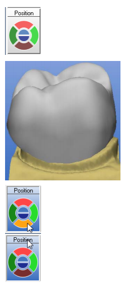 By clicking the “Position” tool, you can activate the positioning function.
With this function you can move the entire restoration (or the selected element) in the following directions:
● mesio-distal
● bucco-lingual
● occlusal-cervical
The restoration can be positioned in two ways:
● step by step, by repeatedly clicking a segment of the circle
● continuously, by keeping a circle segment pressed.
Exit
To exit the positioning tool, click the highlighted button marked “Position”. When you exit the positioning tool, the connection to the preparation margin (base line) is restored.
Rotation tool (Rotate)
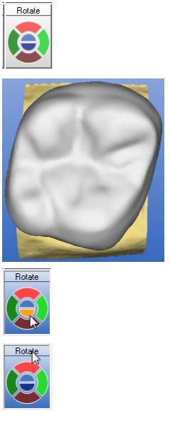 By clicking the “Rotate” tool, you can activate the rotation function.
With this function you can rotate the entire restoration (or the selected element) about the following axes:
● mesio-distal
● bucco-lingual
● occlusal-cervical
The restoration can be rotated in two ways:
● step by step, by repeatedly clicking a segment of the circle
● continuously, by keeping a circle segment pressed.
To exit the rotation tool, click the highlighted Rotate button.
When you exit the rotation tool, the connection to the preparation margin (base line) is restored.
Status bar
 Design window
Design window (3D viewer)
CEREC 3D contains a main window (3D viewer) for visualizing and
designing a restoration in 3D. The 3D viewer opens after all image fields have been acquired. The time up to display of the viewer depends upon the number of image fields and the number of single optical impressions.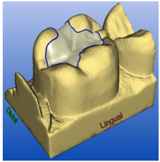 You can do the following in the Design window:
- view the image fields of the preparation, of the occlusion and of the antagonists as well as the restoration, either individually or in any combination,
- determine a new insertion axis,
- hide an image region by entering an open line mesially and distally,
- enter the preparation margin,
- immediately see the effects caused by applying a tool (e.g. editing, scaling …)
- view the restoration in the milling simulation before machining,
- rotate the objects arbitrarily.
- To do so, you press and hold down the left mouse button and move the mouse in the desired direction.
- The direction is indicated for better orientation (e.g. mesial, lingual …).
The objects are displayed centered. You can change the position of the objects with the right mouse button pressed.