3DIEMME Srl is a services Company aimed at Professionals and Companies to provide advice and design in the technical and biomedical field.
Since 2006 the company has worked in the dental and maxillofacial sector supporting Doctors and Dental technicians worldwide in managing clinical cases with minimally invasive and digital technologies.
Among the major services offered by 3DIEMME we highlight the following:
Development and customisation of medical software (3Diagnosys®)
Management of guided surgery procedures using the RealGUIDE technique
Application of rapid prototyping technologies and CAD/CAM in the biomedical field
Support in the preparation of scientific papers and presentations at medical conferences
MISSION
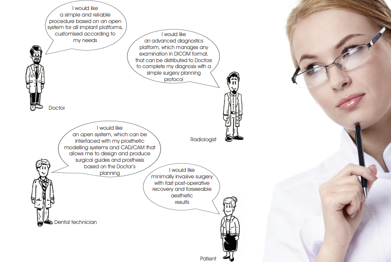
3DIEMME can provide the Customer (Doctor, Dental technician or Industry) a personalised solution for specific needs: ranging from the complete product (software and hardware) to specialised services (software customisation, virtual modelling and multi-material rapid prototyping). Unlike competitors, 3DIEMME can prove the use of its Technology directly on actual problems of the Customers, illustrating the operation of each step to achieve the desired Solution, thanks to the possibility of visiting the production department of the Company and assist the practical manufacturing of Products to be used immediately in solving actual clinical cases.
VISION
To be the reference company for the digital management of minimally invasive surgery via the implementation of software that integrates all the
information required for the Patient’s customised rehabilitation in one open system.
The scope of 3DIEMME is to provide the best solution to integrate the prosthetic planning (from scanners and laboratory modelling software) with the clinical treatment (from diagnosis to computer-assisted bone regeneration to achieve the prosthetic implant and biologically driven design) and implement the resulting project via any CAD/CAM or RP technology available on the Market.
“We shall not cease from exploration,
and the end of all our exploring
will be to arrive where we started
and know the place for the first time”
Thomas S. Eliot
The RealGUIDE procedure is a technique of guided surgery based on the following principles:
• Accurate three-dimensional reconstruction of the Patient by integrating data from X-rays and optical scanning of plaster models or intra-oral scans
• Use of certified software (3Diagnosys) which, in a simple and intuitive way, allows the Clinician to make a complete pre-implant diagnosis and create a virtual surgery plan
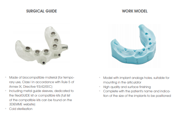
• Using the latest CAD/CAM and rapid prototyping technology for the automatic transfer of the treatment plan to a customised surgical guide and a work model with implant analogs housing to be mounted in the articulator for the construction of temporary prosthesis
• Management of any type of implant rehabilitation intervention
(partial, total and post-extraction edentulism) and bone regeneration (graft anatomical modelling)
• Open system and completely applicable to any implant platform,
which can be fully integrated with the laboratory prosthetic modelling open software for the virtual design of the provisional starting from the implant planning of the Doctor exported in STL format
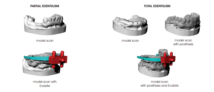
PARTIAL EDENTULISM
TOTAL EDENTULISM

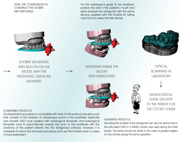
RADIOLOGICAL PROTOCOL
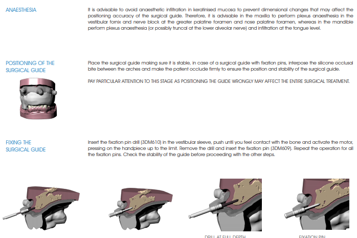
Once the perfect mouth fit of the radiological guide and the Evobite is verified, send the Patient to the Radiology Centre for the tomographic exam.
IMPORTANT: the Patient must be trained to properly position the radiological guide. Show the patient how to fit the guide and do some testing to make sure that the procedure is clear. The radiological guide MUST be preserved and returned to the studio.
Patient positioning
• If possible, remove objects that may introduce artifacts in the images (jewellery, piercing, etc.)
• Make sure that the patient wears the radiological guide correctly
• Place the patient within the acquisition volume of the machine and make sure that he/she remains still during the capture of images
Suggested image capture settings
• Visual field (FOV: Field Of View): sections must have the same field of view that should include all relevant areas, especially the 3DMarkers related to the Evobite
• Capture all of the sections of an exam in the same direction and keep the space between the sections constant (less than or equal to the thickness of the single section)
• Perform a single capture of the Patient with the Evobite in position (it is not necessary to align the acquisition plane with the Evobite)
• Make sure that the 3DMarkers are completely included in the capture volume, as seen in the images below
Exporting images
• Recommended export matrix: 512 x 512 pixels for each image (3Diagnosys can still import matrices of any size)
• Section thickness: use the thinnest available (possibly less than a mm)
• Reconstruction algorithm: use the algorithm with the highest resolution available (Bone or High Resolution)
• Image format: export axial images in uncompressed DICOM 3 format (standard). It is also advisable to export files in series and not compressed into a single file
If the Patient is sent to a Radiological Centre affiliated with 3DlEMME (complete list at www.3diemme.it), specify in the request that the images can be sent directly to 3DlEMME for faster processing. A copy of this protocol can be found on the 3DlEMME website (www.3diemme.it) and attach a copy to the exam request that the Patient will give to the Radiologist.
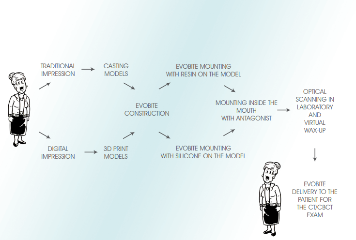
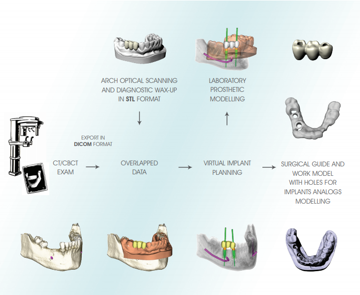
OVERLAPPING DATA
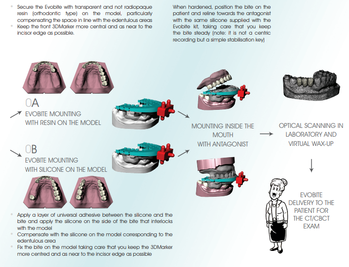
OPTICAL SCAN PROCEDURE OF THE MODELS
The models can be scanned by any laboratory scanner that allows the files to be exported in STL format.
1. Mount the model on the model holder clamp so that it is very stable
2. Perform the scan by paying particular attention to include all anatomical areas, including posterior areas and fornices (if present in the model)
3. Remove the model holder from the scanner and
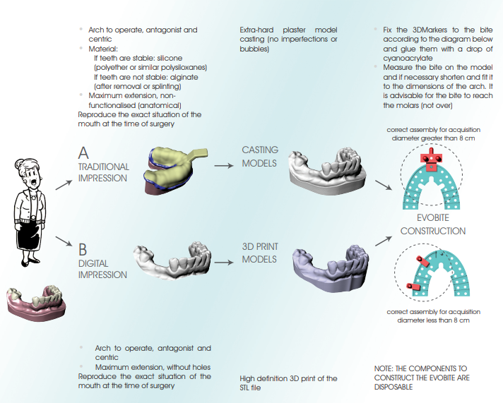
a. FOR PARTIAL EDENTULISM: mount the Evobite while making sure it is secured and there is no risk of it moving during the model holder positioning procedure, and scan (like scanning a wax-up) with particular attention paid to the 3DMarkers regions
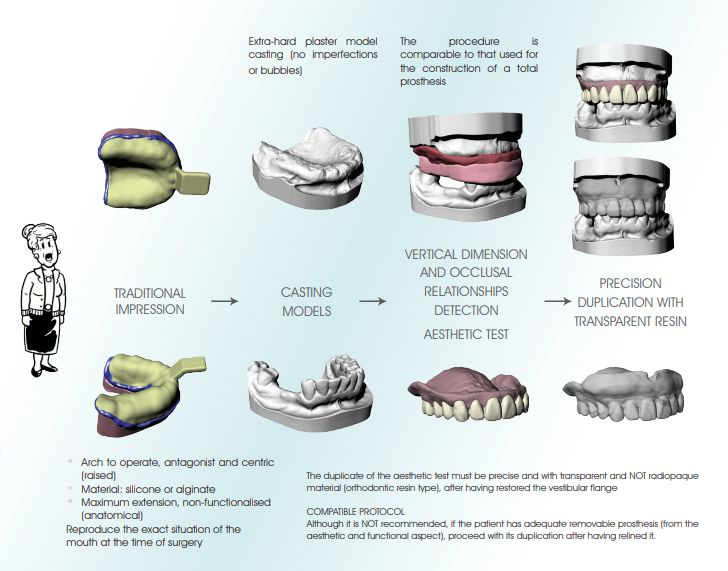
b. FOR TOTAL EDENTULISM: first mount the resin duplicate of the aesthetic test and perform the optical scan (prosthesis scan), then mount the Evobite (without removing the duplicate) and perform another optical scan (Evobite scan) with particular attention paid to the 3DMarkers regions
3. Export scans in separate STL files, with objects placed in the same reference system (i.e. opening the files together you have to be able to see
them correctly mounted like on the original models)
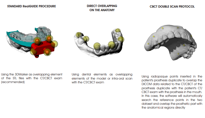
OVERLAPPING PROCEDURE OF STL FILES WITH THE DICOM EXAM
Depending on the STL data available, overlap the STL files with the DICOM dataset in the 3Diagnosys software according to the following alternative protocols (refer to the 3Diagnosys video tutorials for the detailed description):
 VIRTUAL MODELLING
The virtual project of the implants is used for the modelling stage of the surgical guide, the model with the holes correspondent to the implants analogs of the selected implant and the pre-modelling of the provisional prosthesis.
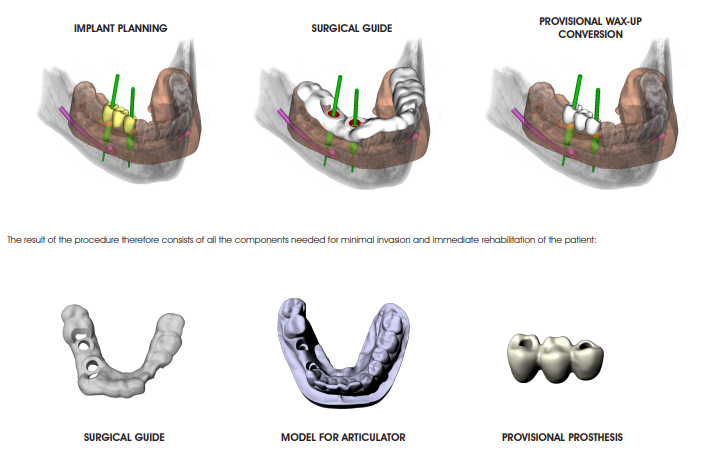
The resulting STL files can be used for production, by means of rapid prototyping and CAD/CAM technologies of all
the components required for the transfer of the virtual design in the patient’s mouth, and in particular:
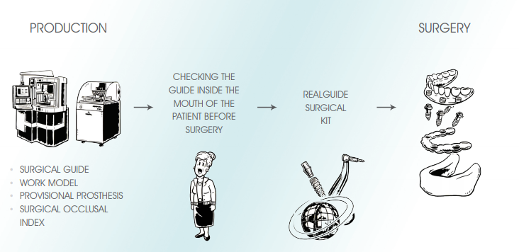
• Construction of the SURGICAL OCCLUSAL INDEX: after mounting the work model and the surgical guide in the articulator, make a occlusal index in silicone with the same rise used for the initial centric
• Constructing the PROVISIONAL PROSTHESIS : from the virtual modelling (integrated with the implants planning, exported from 3Diagnosys), milled with the CAD/CAM technologies available
 PREPARATION DIAGRAM
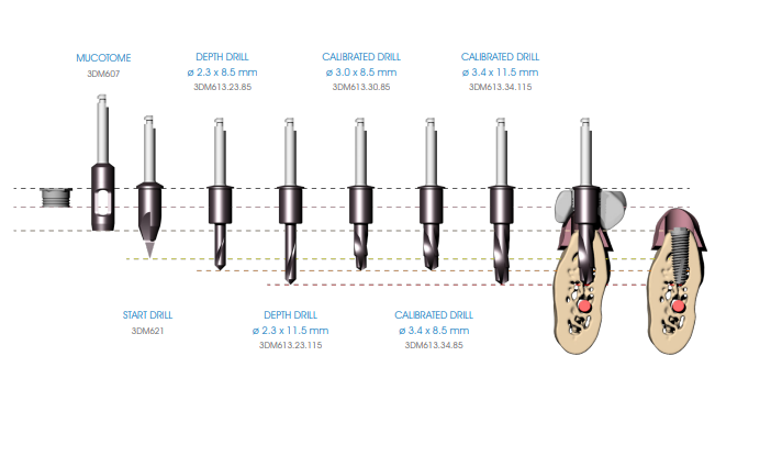
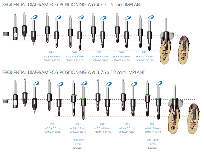
The preparation diagram of the implant site is shown below as an example, for an implant of ø 4×11.5 mm. Refer to the table on page 24 and the description of the various steps of the surgical procedure on page 26 for further details.
 The following illustrates the surgical procedure performed with the instruments discussed above. In order to preserve the vitality of the bone it is important to thoroughly perfuse the surgical area with sterile saline solution at 4°C during surgical manoeuvres.
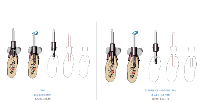
 DEPTH PREPARATION
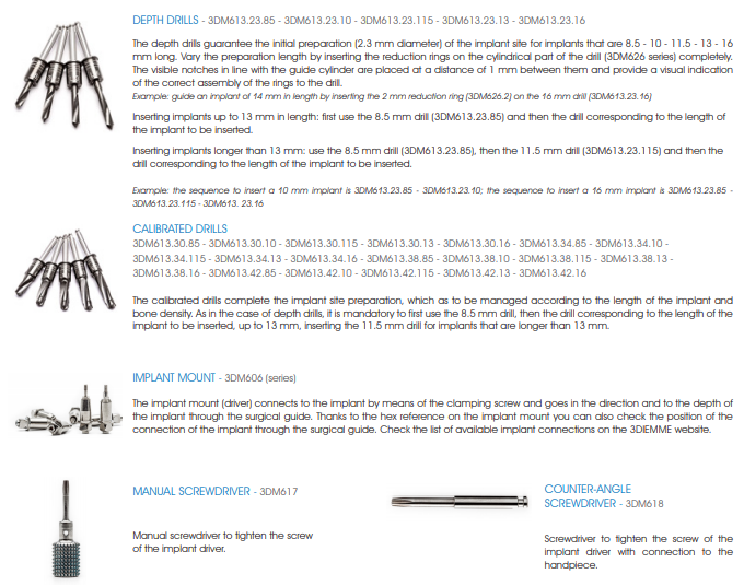
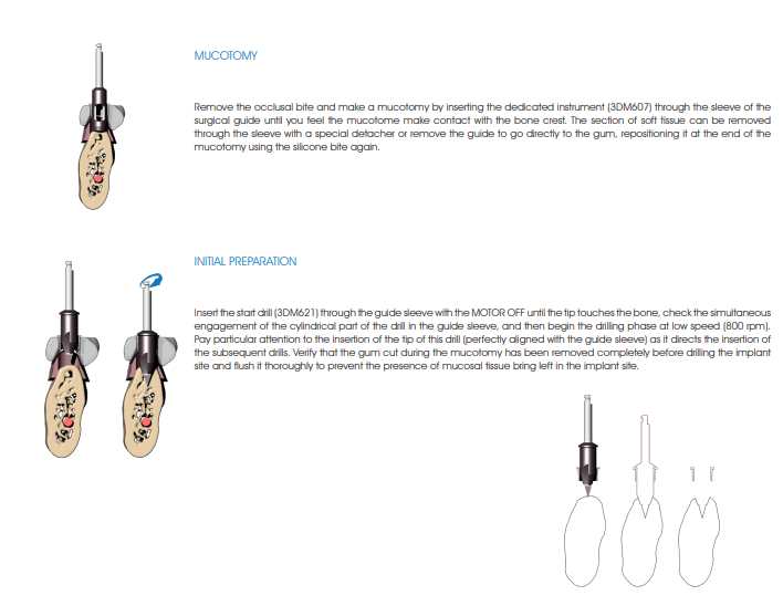
Begin the implant site preparation by inserting the (MANDATORY) first 8.5 mm depth drill (3DM613.23.85) in the guide sleeve of the surgical guide with the MOTOR OFF until the tip touches the bone; check the simultaneous engagement of the cylindrical part of the drill in the guide sleeve, and then begin the drilling phase at low speed (800 rpm). Depending on the length of the implant to be inserted, proceed with the next depth drill according to the following diagram:
• Implants up to 13 mm in length: after using the 8.5 mm drill (3DM613.23.85), insert the drill corresponding to the length of the implant to be positioned (3DM613.23 series).
• Implants longer than 13 mm: after using the 8.5 mm drill (3DM613.23.85), insert the 11.5 mm drill (3DM613.23.115) and then the drill corresponding to the length of the implant to be positioned (3DM613.23 series).
If necessary, mount the drill stops (3DM626) corresponding to the length of the planned implant on the drill. Drill the bone at full drill lenght and at low speed (800 rpm), thoroughly perfusing the implant site after each drilling phase to prevent the bone overheating.
 FINAL PREPARATION
Continue preparing the implant site using the preparation drills (3DM613 series), to be managed according to the length of the implant and the bone density. As in the case of depth drills, it is mandatory to first use the 8.5 mm drill, then the drill corresponding to the length of the implant to be inserted, up to 13 mm, inserting the 11.5 mm drill for implants that are longer than 13 mm.
Insert the drill in the guide sleeve of the surgical guide with the MOTOR OFF until the insertion of the tip of the drill is felt to be entering the hole made in the bone by the previous drill. Verify the simultaneous engagement of the cylindrical part of the drill into the guide sleeve (DOUBLE GUIDE: of the tip in previous hole and of the cylindrical body in the guide sleeve), and then start drilling at low speed (800 rpm).
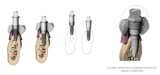
 GUIDED IMPLANT POSITIONING
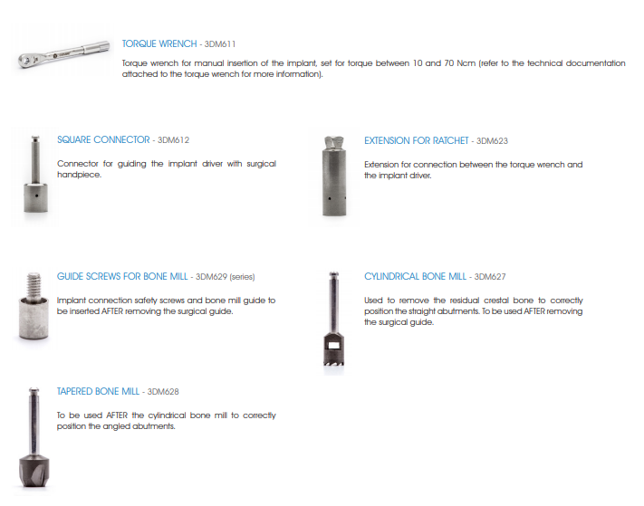
Once you create the implant site, position the implant using the appropriate 3DIEMME implant mount (3DM606 series). Mount the 3DIEMME driver (check that the driver connection is correct according to the implant used BEFORE performing surgery) on the implant and tighten the connecting screw with a manual (3DM617) or handpiece (3DM618) screwdriver (max. 15 Ncm). If it is not possible to easily assemble the implant mount on the implant due to the presence of a pre-mounted driver, remove it and replace it with the 3DlEMME driver.
Insert the implant all the way through the guide sleeve using the square connector (handpiece-driver) (3DM612) or the torque wrench (3DM611) (max 50 Ncm). In case of difficulty in positioning due to excessive insertion torque of the implants, remove the implant and prepare with the drill that has a larger diameter or tap with a dedicated tool according to the surgical site. In the case of use of angled abutments it is important that the hexagon present in correspondence with the head of the driver aligns with the hexagonal profile of the sleeve inserted in the surgical guide.
Keep the driver in place while proceeding to the insertion of the next implant (to increase the stability of the surgical guide). In case of multiple implants, it is advisable to insert implants alternating the right site with the left site in order to avoid the surgical guide from possibly rotating with respect to the centre of gravity. Keep in position at most two or three drivers (depending on the number of implants to be inserted) to avoid generating excessive tension in the surgical guide.
 GUIDE REMOVAL
At the end of the insertion phase remove in the following order: the fixation pins of the surgical guide, the connecting screws and drivers inserted to remove the surgical guide.
Verify the possibility of the correct coupling of the prosthetic components correctly, thereby eliminating any excess soft tissue and residual bone crests that can interfere with the mounting of the abutments.
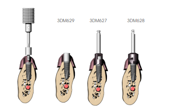
ADJUSTING THE BONE CREST
Mount the connection safety screw and bone mill guide (3DM629 series) (verify that the connection of the screw is correct according to the implant used BEFORE performing surgery); insert the cylindrical bone mill (3DM627), if straight abutments are used, with the motor off until engagement with the guide cylinder of the screw; then proceed at low speed until the stop is reached. It is recommended not to press the handle all the way and work with an oscillating movement so as not to overtighten (indirectly) the protection screw making it difficult to remove it from the implant. If angled abutments are planned also use the tapered bone mill (3DM628) to allow the abutment to be housed adequately even in cases of irregular bone crests. Remove the protection screw when finished.